1
\$\begingroup\$

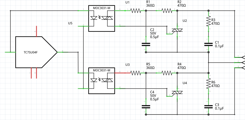
I need to design a circuit that implements an SPDT switch using Triacs and Optoisolators. Currently I am implementing this with two pairs of Optoisolated Triacs with one having inverted signal from the uC. Hence at all times, 1 of the Optoisolated Triacs is "ON" and the other is "OFF". However, under no power condition, both the pairs the act as NO circuits.

Input to the Not Gate comes from the uC

I need to Switch 220V AC with 3.3V DC current.

Kindly help me build a circuit where even under no power conditions, I have 1 NO and 1 NC path available.

\$\endgroup\$
2
  • 2
    \$\begingroup\$ The problem with electronic devices is they have a habit of not working without an external power supply. On the other hand electro-mechanical devices do. Why not just use a relay. \$\endgroup\$ Commented Jun 20, 2016 at 10:35
  • 1
    \$\begingroup\$ @JImDearden because of the lower life expectancy of electro-mechanical devices. An E-M Relay has moving parts which significantly reduces its life. \$\endgroup\$ Commented Jun 20, 2016 at 15:49

1 Answer 1

2
\$\begingroup\$

If I understand you correct, you don't want to control the 2 triacs independently, but you always want one of each to be triggered (even if your microcontroller circuit is powered off).

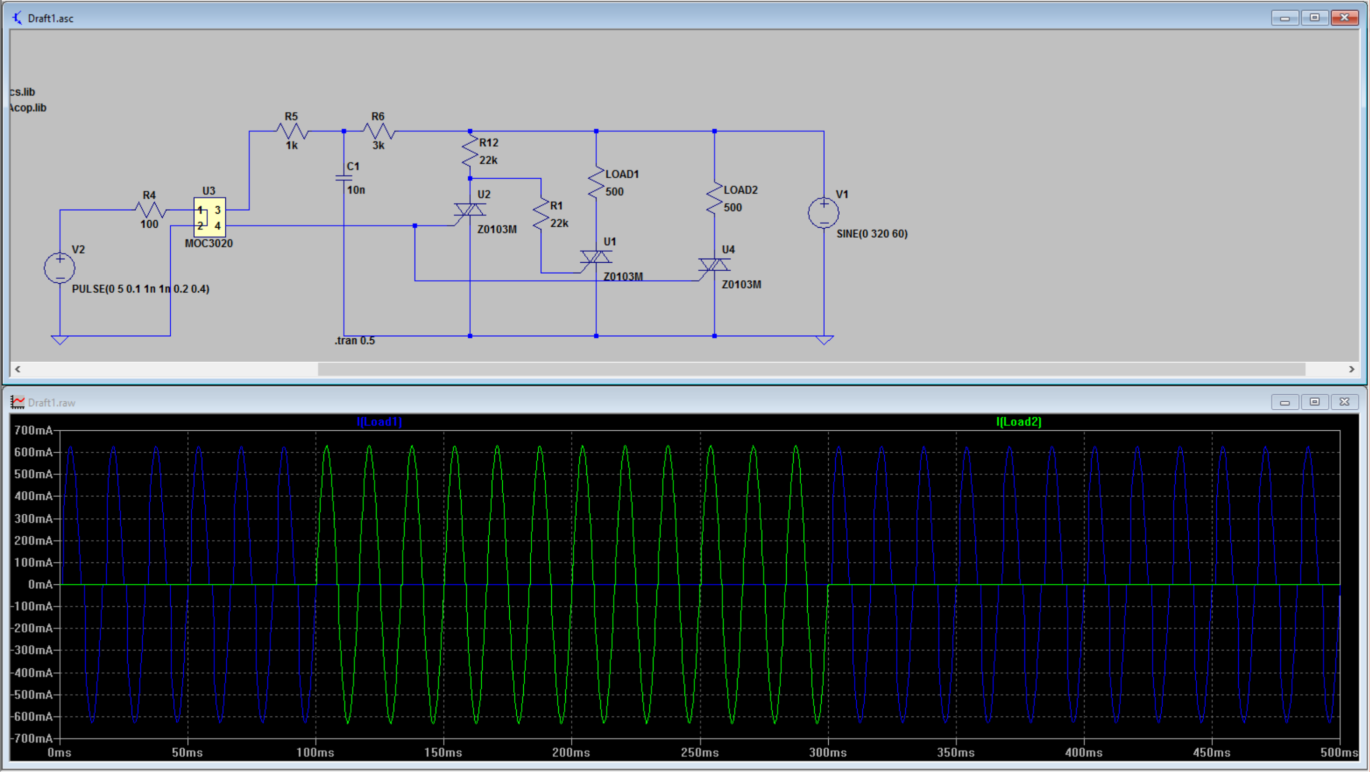
This can be done by cascading the triacs. Please see below circuit

This circuit also has the advantage that only 1 MOC30xx is needed. But it has the disadvantage that LOAD1 must be connected (and a small current will flow through it, even if powered off) for it to work and it can not be a high resistive load as otherwise the trigger current for U1 is getting too low to trigger.

(values are only roughly chosen because I was not 100% sure and wanted to proof the concept)

This can be fixed by adding a 3rd triac. Here you have to be careful that the trigger current coming from your MOC30xx (and the snubber network) is high enough to trigger 2 triacs.

(values are only roughly chosen because I was not 100% sure and wanted to proof the concept) enter image description here
Please be careful when you calculate the resistor values (in your circuit the snubber network resistors are all quit low, so I guess you are not running this on mains voltages. However, when you want to run it on mains voltages carefully calculate the resistor values, some of them have to dissipate quite a lot of power!

To calculate the snubber network you can follow this application note for the MOC3031 (if you've not already done it).

\$\endgroup\$
3
  • \$\begingroup\$ Thanks a ton, @KarlKarlson. Your answer is very informative, but the circuit I need needs to be 'Plug-and-Play', i.e, Something that can easily replace an SPDT Switch without any changes to the wiring. Also, I intend to use this circuit on Mains (230V AC) and having current flowing through the loads is not an option. The loads may or may not be high resistive. Point me in the right direction? :) Again, thanks a ton! \$\endgroup\$ Commented Jun 20, 2016 at 16:04
  • 2
    \$\begingroup\$ Then, once again, use a relay. The lifetime of a relay isn't measured in hours, or days, or even years as long as the load conditions aren't excessive. \$\endgroup\$
    – R Drast
    Commented Jun 20, 2016 at 16:25
  • \$\begingroup\$ "having current flowing through the loads is not an option." -> then use the second circuit. But I think I still don't get the last bit of your question. Where do the 3.3V come from? You want the SPDT switch on the isolated side for safety I guess? Then just switch the M30xx with a switch and a resistor on that side. \$\endgroup\$ Commented Jun 21, 2016 at 10:33

Your Answer

By clicking “Post Your Answer”, you agree to our terms of service and acknowledge you have read our privacy policy.

Not the answer you're looking for? Browse other questions tagged or ask your own question.