1
\$\begingroup\$

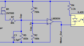
I am currently working with the LM393N and am inconsistently getting a high output when it should be low. Below is a schematic showing the inputs and outputs of the IC.

Comparator Inputs and Outputs

VCC is coming from a "12V" rail supplied by a 12V zener with a 5K current limiting resistor and a 47uF cap in parallel (I know it's not ideal but I'm on a budget!).

The comparator is supposed to output a low signal, turning on the IL420 phototriac, when the capacitor (C1 on schematic) is discharged below around 1.5V. The expected output can be seen in the circuit simulation below. What's actually happening is the output stays high regardless of the capacitor voltage...... sometimes. Perhaps the most frustrating thing about this is that the problem only occurs occasionally, if I had to estimate it's probably around 10% of the time, the rest of the time the circuit performs its job admirably.

Comparator Waveform Output

What I've already tried/checked:

  • The LM393N output is open-collector so I thought that the combination of the 3.3K resistor and LED internal to the IL420 may not be behaving as a suitable pull-up resistor, so I put a 4.7K resistor from VCC to the output. No dice.

  • The input common mode range is listed on the datasheet as 0 to VCC-1.5V max, so I put the 40K resistor in between the source pin of the 2N7000 and the comparator input to ensure that the voltage wouldn't exceeded 9.5V (the voltage across the zener occasionally dips to 11.5-ish but I believe the input voltage stays within range).

  • Maybe this goes without saying but I've checked that the cap is fully discharging, the (+) input is getting 1.5V and that the output is high when it shouldn't be.

Note - I know using an N-Channel MOSFET to drive a load on the source isn't necessarily best practice but this is a rough prototype at the moment.

Note numero dos - It's also worth mentioning that I am using both comparators on the chip and the other behaves as expected, at least so far.

Thanks for any and all help,

\$\endgroup\$
6
  • 1
    \$\begingroup\$ A better title would be "Wrong expectation of LM393s behaviour" \$\endgroup\$
    – PlasmaHH
    Commented Jun 20, 2016 at 20:45
  • \$\begingroup\$ Would you mind elaborating? The other element behaves as I expect it, and this one behaves the way I want it to most of the time... \$\endgroup\$
    – nreath
    Commented Jun 20, 2016 at 20:59
  • \$\begingroup\$ Did you try swapping these elements? \$\endgroup\$
    – rdtsc
    Commented Jun 20, 2016 at 21:03
  • \$\begingroup\$ The schematics doesn't show how you are driving M1's gate. Maybe M1 is staying ON when it should not. It would be useful that you show this part of the schematics. \$\endgroup\$
    – Roger C.
    Commented Jun 20, 2016 at 21:11
  • \$\begingroup\$ What is happening to the capacitor voltage when the 393 is NOT working properly? \$\endgroup\$ Commented Jun 20, 2016 at 21:30

1 Answer 1

2
\$\begingroup\$

It appears you are experiencing "latchup" which can occur when the input is higher or lower than the rail. You have a big capacitor which can hold a charge when the power fluctuates. You can try putting a schottky diode (reverse biased) between signal cap_th and ground and cap_th and the rail which might solve it.

\$\endgroup\$
5
  • 2
    \$\begingroup\$ Good point. The 5k current limiting resistor may cause the supply voltage to drop below that of the cap when under load. \$\endgroup\$
    – Transistor
    Commented Jun 20, 2016 at 21:46
  • 1
    \$\begingroup\$ Just what I thought! \$\endgroup\$ Commented Jun 20, 2016 at 21:50
  • \$\begingroup\$ That's interesting, and definitely something I wouldn't have thought of. I've definitely seen the voltage dip, specifically when the MOSFET turns on. I'm no longer at work but I'll test your solution tomorrow and report back. \$\endgroup\$
    – nreath
    Commented Jun 20, 2016 at 21:55
  • 1
    \$\begingroup\$ The choice of Schottky needs to be carefully done - the capacitor charging current is in the range of some devices reverse leakage current when warm. \$\endgroup\$ Commented Jun 21, 2016 at 6:56
  • \$\begingroup\$ I scoped the rail to see how much the voltage across the zener dipped when put under load, then simply changed the 40K resistor to a 60K, seems to have solved the problem. \$\endgroup\$
    – nreath
    Commented Jun 21, 2016 at 12:09

Your Answer

By clicking “Post Your Answer”, you agree to our terms of service and acknowledge you have read our privacy policy.

Not the answer you're looking for? Browse other questions tagged or ask your own question.