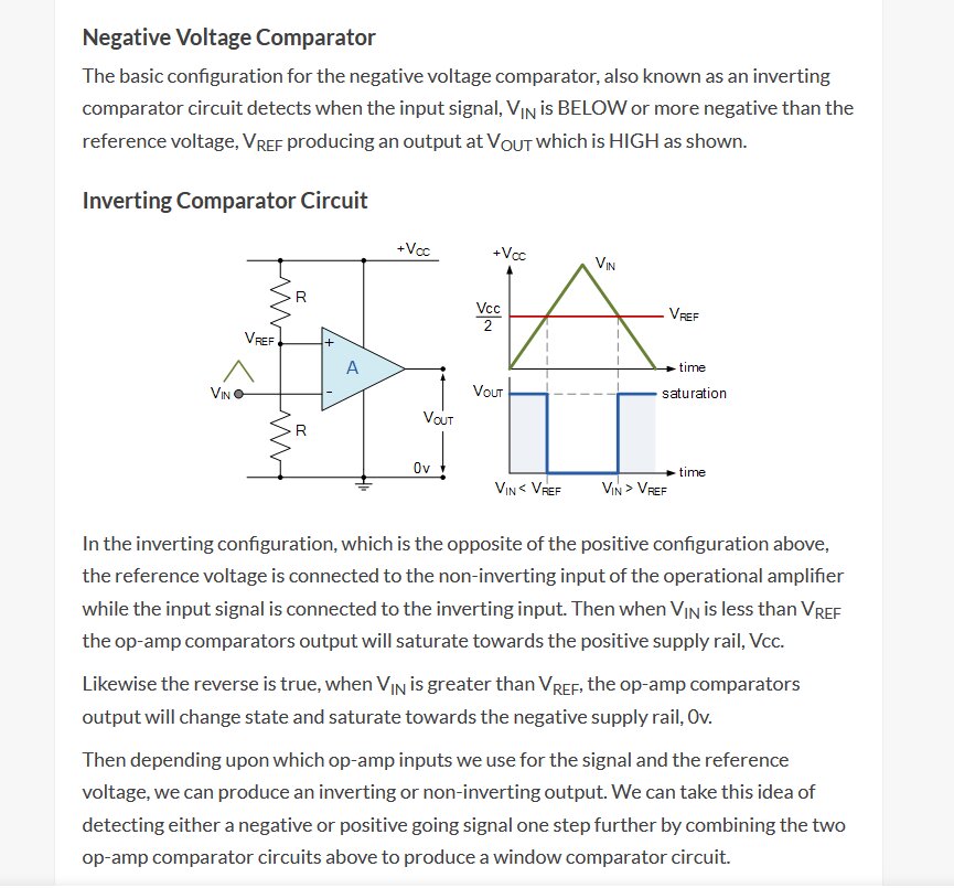
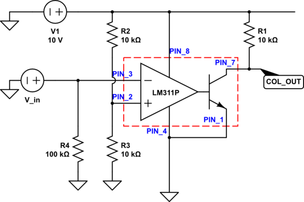
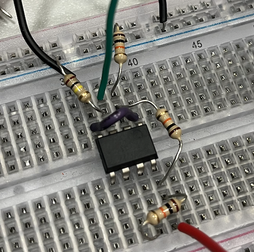
What you've put together is an inverting comparator circuit.
So which signals are you trying to compare? It looks to me like whatever's going into V_in is being inverted by the inverting input (-, pin_3), while your non-inverting input (+, pin_2) is getting fed 5V from V1 through the voltage divider.

Your reference voltage is the voltage-divided 5V, and your V_in, between 2-8 or 0-9V, is always going to be "less than" V_ref because the inverting input inverts whatever value you put into it. +ve voltages become -ve, -ve become +ve, so the op-amp is saturating towards the negative rail of the chip, which in your case, is ground, and so it rests around 1.43V because of losses/gains throughout the circuit's componentry (theoretically, you'd see "0V", but that's not the real-word state of the component's materials).
Whatever goes into the inverting input, in your case, 3V or 8V, is going to be -3V or -8V to the op-amp in the LM311. Whatever inverted voltage on pin 3 is what'll be compared against whatever's going into the non-inverting input, in your case, only 5V.
From the datasheet:
"A typical LMx11 application compares a single signal to a reference or two signals against each other. Many users take advantage of the open-drain output to drive the comparison logic output to a logic voltage level to an
MCU or logic device. The wide supply range and high voltage capability makes LMx11 optimal for level shifting to a higher or lower voltage."
and...
"The LMx11 operates solely as a voltage comparator, comparing the differential voltage between the positive and
negative pins and outputting a logic low or high impedance (logic high with pullup) based on the input differential
polarity."
To be clear, when it's talking about the positive and negative pins, it means the non-inverting and inverting inputs, + and -, not the positive and negative supply voltages (Vcc+ and Vcc-).
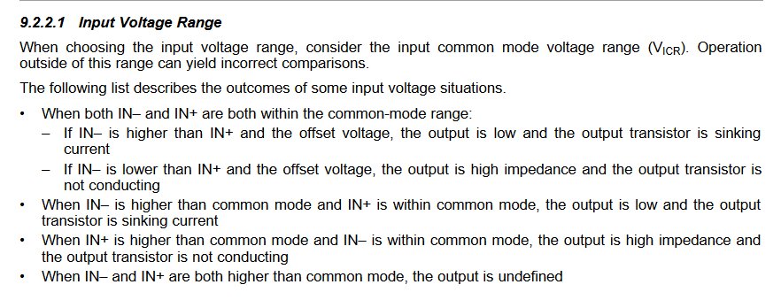
This is something characteristic of most chips that involve op-amps, that is, the range between Vcc+ and Vcc-, what the datasheet refers to as "input common mode voltage range". Since you're grounding the negative supply voltage pin, you're reducing the range with which you can compare your inputs on the inverting or non-inverting pins.

(For reference, it recommends -14.5V at most and at least 13V for lower and upper range limits, respectively. And on that note, when in doubt, dig into the datasheet. There are almost always test circuits for applications the component can be used for.)


