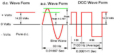
I have a digital signal, similar to RS232, but at +15/-15. It is a non-sine wave and is used to also power DC motors and other devices (address coding, information, and power). I want to measure from a very low 10ma to a max or 3-4A.
I do not want to use a hall effect coil as that uses expensive real estate on the PCB and tends to be bulky and requires the user to wire it into the circuit during construction vs adding it in at a later date. Also, if a device fails, being hardwired into a circuit would require more work than a device cut into the circuit being monitored.
I have attempted to use the ASC712 (hall effect IC), but get a very large swing in output voltage along with "noise" being present even though there is no current flowing. Also, the output voltage is centered around 2.5v, which limits the sensitivity of the output to the ADC to 511 steps. The voltage swings may be cured using RC to smooth out the output?
I have also tested using the ZXCT1021 device from Zetex, with unsatisfactory results. I have attempted to place 1N914 diodes between the sense resistor and the sense inputs so I only measure the +15 volt side. This does not work. The output is very noisy and read fluctuations even though there is no current draw being applied.
I have been looking at the LTC1601 in a dual direction configuration using the same sense resistor. This give me two outputs, one for each direction. Maybe the outputs tied together as shown in the design. Should I have diodes in line and maybe RC for smoothing?
Anyone have experience in measuring the current flow this type of signal?
Here is an example of the 3 different wave forms. The first is easy to measure as it is DC. The second is AC and measuring it is also well documented. The last waveform is what I am working with. It is more of a pulsed form.


