0
\$\begingroup\$

I have a digital signal, similar to RS232, but at +15/-15. It is a non-sine wave and is used to also power DC motors and other devices (address coding, information, and power). I want to measure from a very low 10ma to a max or 3-4A.

I do not want to use a hall effect coil as that uses expensive real estate on the PCB and tends to be bulky and requires the user to wire it into the circuit during construction vs adding it in at a later date. Also, if a device fails, being hardwired into a circuit would require more work than a device cut into the circuit being monitored.

I have attempted to use the ASC712 (hall effect IC), but get a very large swing in output voltage along with "noise" being present even though there is no current flowing. Also, the output voltage is centered around 2.5v, which limits the sensitivity of the output to the ADC to 511 steps. The voltage swings may be cured using RC to smooth out the output?

I have also tested using the ZXCT1021 device from Zetex, with unsatisfactory results. I have attempted to place 1N914 diodes between the sense resistor and the sense inputs so I only measure the +15 volt side. This does not work. The output is very noisy and read fluctuations even though there is no current draw being applied.

I have been looking at the LTC1601 in a dual direction configuration using the same sense resistor. This give me two outputs, one for each direction. Maybe the outputs tied together as shown in the design. Should I have diodes in line and maybe RC for smoothing?

Dual Flow Circuit

Anyone have experience in measuring the current flow this type of signal?

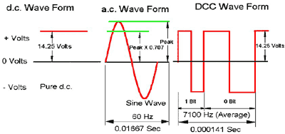
Here is an example of the 3 different wave forms. The first is easy to measure as it is DC. The second is AC and measuring it is also well documented. The last waveform is what I am working with. It is more of a pulsed form.

Different wave forms

\$\endgroup\$
6
  • \$\begingroup\$ Can you measure on the return (gnd) side? \$\endgroup\$
    – winny
    Commented Jun 21, 2016 at 6:44
  • \$\begingroup\$ Do you want to measure the instantaneous value of the current or RMS? \$\endgroup\$
    – filo
    Commented Jun 21, 2016 at 7:07
  • 1
    \$\begingroup\$ What frequency range does the noise have and what transient rates of current do you have? \$\endgroup\$ Commented Jun 21, 2016 at 7:38
  • \$\begingroup\$ @ winny - I did not think to look at that side as the reference. I will test that with the ZXCT1021 as the ASC712 does not have an easy way to test to the "neutral" line. \$\endgroup\$ Commented Jun 21, 2016 at 15:33
  • \$\begingroup\$ @filo - I am looking to determine the current flow. As it is a non-sine AC signal (think of it looking like an RS232 signal, only at 15v vs 12v and capable of powering up to 10 amps), RMS does not work. It is not a uniform wave but a series of wider and shorter pulses moving from 0 to +15 to -15, back to 0. The pulses provide both power (rectified to DC to run circuits and DC motors) and information (like RS232). \$\endgroup\$ Commented Jun 21, 2016 at 15:51

1 Answer 1

1
\$\begingroup\$

I can recommend the Sensitec CMS3005 for your requirements. It has good signal to noise ratio, no digital parts (no spurs) and wide bandwidth (2MHz) with reasonable linearity (<0.2%). It's galvanically insulated and works similar to hall-effect ICs but has a more sensitive AMR magnetic field sensor.

I have used the CMS3025 in a very demanding application and have been very satisfied with the results.

The downsides are the dual +-12V supply as well as the higher price compared to hall effect ICs. It also has a quite large package.

Sensitec has also current measurement ICs for single supply applications, as well as more compact chips (e.g. the CFS1000), but I have no personal experience with them.

\$\endgroup\$

Your Answer

By clicking “Post Your Answer”, you agree to our terms of service and acknowledge you have read our privacy policy.

Not the answer you're looking for? Browse other questions tagged or ask your own question.