3
\$\begingroup\$

The exact question is the following:

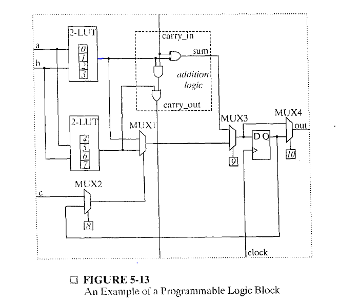
For the programmable logic block shown in Figure 5-13, show the necessary configuration settings to implement each of the following types of circuits. You can assume that the upper data input of each multiplexer is chosen with a select input of 0. (a) A combinational function of inputs a, b, and c. (b) A Moore machine (c) A Mealy machine

Figure is the following: enter image description here

When it asks for the combinational function, I think it is asking about the truth table. And from that I can draw the moore and mealy machines too. But the problem is that I'm unable to figure out the outputs of the two LUTs. There are 4 combinations of inputs possible for each but what is the output value of each of those inputs? I'm also unable to figure out the meaning of the vertical line in middle of the dotted box (labelled as addition logic). Any help is appreciated.

(The question is from the book "Logic and Computer Design Fundamentals page number 321, 5th edition)

\$\endgroup\$
5
  • \$\begingroup\$ Hint: you don't care about the configuration of the LUT. They will just be arbitrary logic functions of a and b, allowing you to use those inputs. The carry processing is also extraneous to the problem. Look just at the four multiplexers and the three (!) control locations for multiplexers. \$\endgroup\$ Commented Jun 30, 2016 at 0:33
  • \$\begingroup\$ @user2943160 then how can I show a combinational function of a, b and c? I can get c, yes. Using c and 8, 9, 10, I can get the output in terms of f(a) and f(b) but how to find out function in terms of a, b, c without looking at the LUT configuration? \$\endgroup\$
    – aste123
    Commented Jun 30, 2016 at 0:47
  • \$\begingroup\$ Notice that the input c can control MUX1 if control 8 is set to 0. This allows a 3-input logic function to be implemented, using both 2-LUT outputs. \$\endgroup\$ Commented Jun 30, 2016 at 0:49
  • \$\begingroup\$ @user2943160 what confuses me is that by setting 8 to 0 the 3 input logic function would be created in terms of f(a), f(b) and c i.e f(f(a), f(b), c) instead of f(a, b, c). Can you tell me where I'm wrong. \$\endgroup\$
    – aste123
    Commented Jun 30, 2016 at 0:58
  • \$\begingroup\$ That's still a valid combinational function, better put as \$f_{mux}(f_{LUT_1}(a,b), f_{LUT_2}(a,b),c)\$. Please also see my more extensive answer below. \$\endgroup\$ Commented Jun 30, 2016 at 1:00

2 Answers 2

1
\$\begingroup\$

From the problem statement:

show the necessary configuration settings to implement each of the following types of circuits.

The points of concern, then, are the configuration values 0 through 10. However, the controls 0 through 7 are the values to implement the logic functions of the two 2-LUT blocks. Thus, the question is referring to the values to choose for controls 8, 9, and 10.

When it asks for the combinational function, I think it is asking about the truth table.

You do not need the complete truth table. Because the functions implemented by the 2-LUTs are arbitrary, you cannot determine the truth table. However, you can examine the configuration of the multiplexers to implement a combinational function. Notice that the input c can control MUX1 if control 8 is set to 0. This allows a 3-input logic function to be implemented, using both 2-LUT outputs. The implemented function would be \$f_{mux}(f_{LUT_1}(a,b), f_{LUT_2}(a,b),c)\$, which, in binary, covers all possible 3-input logic functions.

I'm also unable to figure out the meaning of the vertical line in middle of the dotted box (labelled as addition logic).

The addition logic box is mostly irrelevant to these questions. The vertical signals are actually labeled: carry_in and carry_out. The dedicated logic for adders improves the efficiency in using the logic block in a wide adder. That logic is selected by control 9 being set to 0. Likely, that is not required, so you want control 9 to be set to 1 to only use the MUX1 output.

Differentiating the Moore and Mealy implementations in exactly one logic block is also done through control 8. With a value of 1 at control 8, the output of the register can feed back to be a term in the combinational logic, acting as the third input by controlling MUX1.

Completing the solution to any of the three parts requires choosing the value for MUX4 as appropriate for the logic or state machine implementation.

\$\endgroup\$
2
  • \$\begingroup\$ so, is the aim to find a combinational function for the 2 LUTs only without taking into account the whole circuit (i.e the control pins 9 and 10)? (also keeping control bit 8 = 0 always) \$\endgroup\$
    – aste123
    Commented Jun 30, 2016 at 1:09
  • \$\begingroup\$ @aste123 I have added some more clarifications. You are analyzing the control pin, but only need to choose values for certain ones. See the first section of my edited answer. \$\endgroup\$ Commented Jun 30, 2016 at 1:17
0
\$\begingroup\$

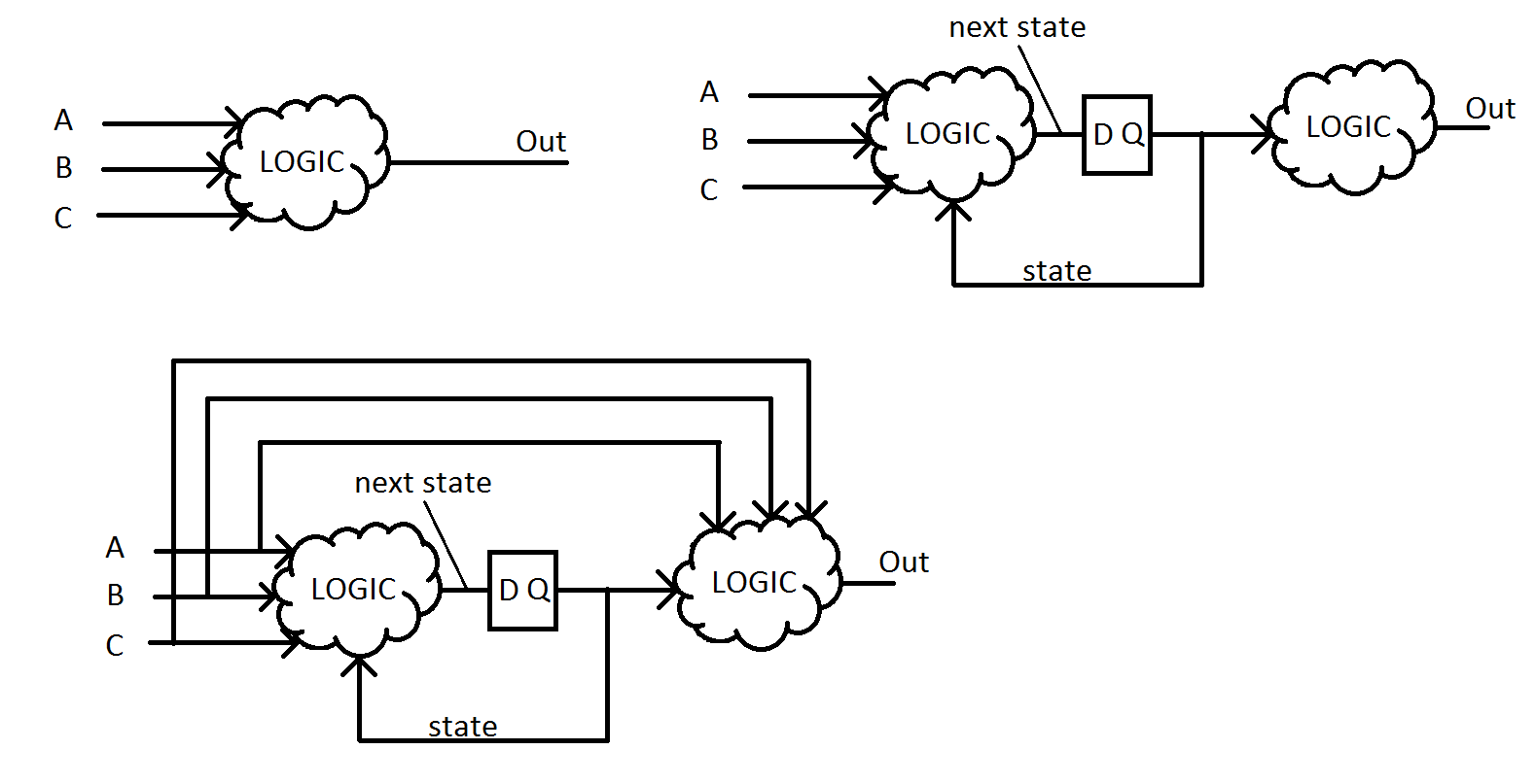
I think the misleading part about this question is that it has several different constructs to implement logic, most of which are irrelevant to solving the question. It's all about having the correct routing. The LUTs can be considered a block of logic, the summation/carry block could be considered a block of logic, even a straight connection could be considered a block of logic (smallest truth table ever).

Check out these diagrams of the 3 parts of the question and see if you can envision how the muxes would need to be configured to allow the data to flow.

enter image description here

\$\endgroup\$

Your Answer

By clicking “Post Your Answer”, you agree to our terms of service and acknowledge you have read our privacy policy.

Not the answer you're looking for? Browse other questions tagged or ask your own question.