7
\$\begingroup\$

As far as I understand the flyback topology, it can be used in both buck and boost converters.

What I am not sure about is: Does it also work for the case where buck-boost is needed, i.e. \$V_{\text{in,min}} \leq V_{\text{out}} \leq V_{\text{in,max}}\$?

I think it should, but googling the topic immediately leads to the SEPIC converter. Also, I know that isolated SEPIC is possible, but I rarely see design examples.

Could you give me some idea on what topology to use for the specific case of:

\$9 < v_{\text{in}} < 24 \text{V}\$ for \$v_{\text{out}} = 12 \text{V}\$ at 1 A, galvanically isolated

\$\endgroup\$
1
  • 1
    \$\begingroup\$ Non-isolated flyback must have output such that Vin cannot "run into " Vout during off periods. So it allows +Vout >+ Vin or -Vout of any value for +Vin. For isolated converter input can never "run into" output so Vout sign and amplitude can be independent of Vin. \$\endgroup\$
    – Russell McMahon
    Commented Jul 17, 2016 at 15:42

3 Answers 3

8
\$\begingroup\$

Yes, a flyback converter can masquerade as a buck-boost converter: -
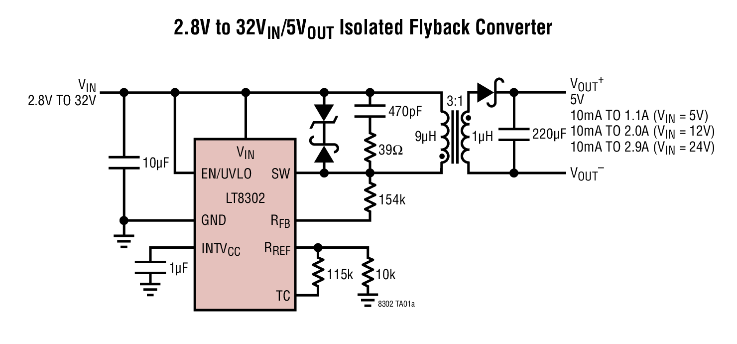
enter image description here

This one from LTI also negates the need for an opto-isolator by sampling the back emf in the primary - that back emf is indicative of the secondary voltage so it's quite a useful little device.

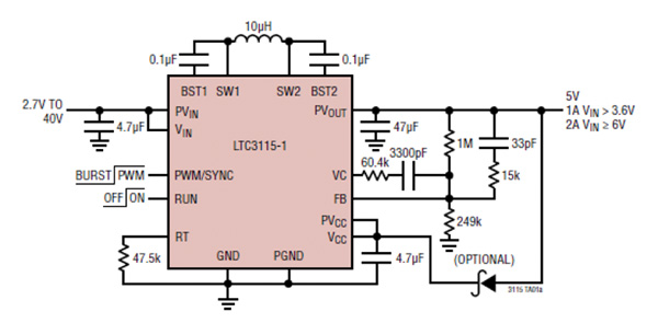
Compare that with a buck boost offered also by LTI: -
enter image description here

There are advantages and disadvantages with the buck-boost. Firstly there is no output isolation but it doesn't require a minimum load and will be 5% or so more energy efficient.

So, you may ask, how does the flyback converter generate higher output voltages than the input when it appears to use a step down transformer. This is acheived by PWM effectively altering the transformer turns ratio (to put it crudely).

Think of the output load as requiring so-much power to acheive a certain regulated output voltage; the fly-back design transfers energy stored in the primary to the secondary each switching cycle and that energy transferred, multiplied by the number of cycles per second = power transferred. In other words it doesn't work like a normal transformer because you can, on the face of it, have what seems to be a step down ratio yet a higher voltage is produced due to the flyback effect.

Clearly, if you want a lower voltage on the output compared to the input you want your output winding to be low inductance so that it can supply more current to the heavier load but, it's not a hard and fast rule.

\$\endgroup\$
1
  • \$\begingroup\$ Thanks for the explanation! Also, the first LT controller you suggested, seems perfect for the job. I am a bit amazed that I did not found too much alternatives for it, though. As least not with integrated switch plus PSR (no-opto) ;-) \$\endgroup\$
    – Junius
    Commented Jul 17, 2016 at 17:58
5
\$\begingroup\$

Flyback converter is derived from buck-boost converter by adding a secondary winding to the inductor. Buck-boost can produce output voltage with absolute value both lower and higher than the input. So can a flyback converter. The secondary winding does two things. (1) It helps create galvanic isolation. (2) It allows to change the sign of the output.

An isolated 12V 1A converter falls squarely into the flyback territory. A push-pull converter, a forward converter can do this job too. Be aware of one practical issue, though. Transformers and flyback inductor-transformers can be difficult to source. (I wrote about that earlier.) So, it's possible that the design of your converter will be dictated by the off-the-shelf magnetics (unless you can create your own custom magnetics).

\$\endgroup\$
3
\$\begingroup\$

Switched converters store the energy needed at the output as magnetic energy in the inductor.

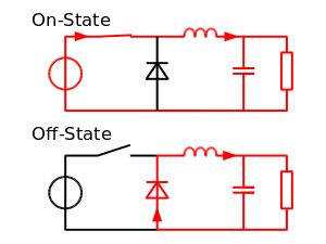
A standard buck converter has the inductor in series with the output meaning that the inductor can only be charged (with the right polarity) if Vin > Vout

buck converter

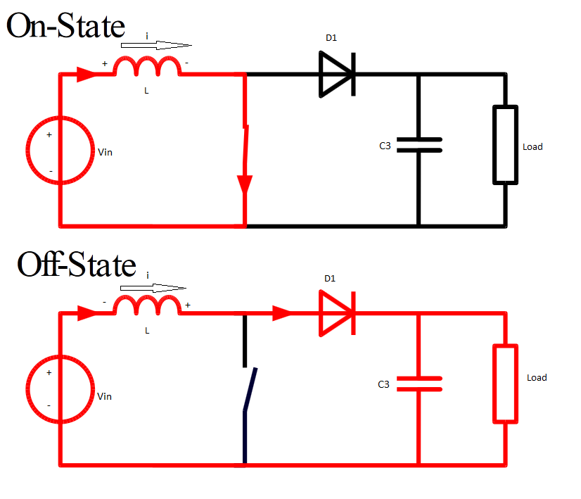
A boost converter charges the inductor directly from Vin and discharges the inductor while it is in series with Vin and this results in Vin < Vout as the voltage from the inductor and Vin are added.

enter image description here

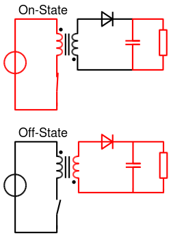
A Flyback converter uses a transformer in place of the inductor and the energy is extracted from the secondary side. This separates the charging and discharging circuits. You can discharge in whatever way you like. You're not limited to adding or subtracting the voltage from the inductor from Vin ! The secondary winding is isolated, you can connect it however you like.

enter image description here

So any Flyback based converter should be able to make the desired output voltage as long as it is able to charge the inductor/transformer enough to be able to provide the required output power at the required maximum voltage. For lower output voltages it can simply lower the duty cycle of the primary side switch.

\$\endgroup\$
2
  • \$\begingroup\$ The problem with SEPIC is that it's a nasty one to isolate or run high currents through because of that cap in the middle \$\endgroup\$ Commented Jul 17, 2016 at 14:11
  • \$\begingroup\$ Uhm I wrote Sepic but I should have written flyback ! Duh \$\endgroup\$ Commented Jul 17, 2016 at 14:47

Your Answer

By clicking “Post Your Answer”, you agree to our terms of service and acknowledge you have read our privacy policy.

Not the answer you're looking for? Browse other questions tagged or ask your own question.