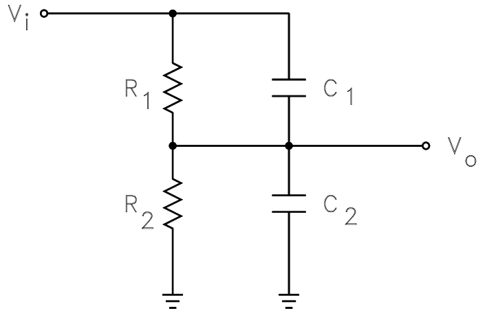
This is the typical example where the Fast Analytical Circuits Techniques (FACTs) will help you get the answer without writing a line of algebra. Look at your circuit for \$s=0\$: remove all caps. The dc transfer function is a simple resistive divider: \$H_0=\frac{R2}{R1+R2}\$. What is the time constant of this circuit? Reduce the excitation source (\$V_{in}\$) to 0 V and "look" at the resistance driving the capacitors. As you can see, both capacitors come in // forming a single cap. equal to \$C_1+C_2\$. This is what we designate as a degenerate case (1 single independent state variable despite the 2 energy-storage elements). The time constant is \$\tau=(R_1||R_2)(C_1+C_2)\$. So the pole is simply the inverse of \$\tau\$: \$\omega_p=\frac{1}{(R_1||R_2)(C_1+C_2)}\$. Is there a zero in this circuit? Yes, if the impedance \$Z\$ made of \$C_1\$ and \$R_1\$ becomes infinite at the zero frequency, the response disappears and this is your zero. What is the pole of this network (the value of \$s\$ for which \$Z\$ becomes infinite)? The time constant is \$R_1C_1\$, then the zero of this circuit is \$\frac{1}{R_1C_1}\$. The complete transfer function in a clean and ordered form is thus:
\$H(s)=H_0\frac{1+s/\omega_z}{1+s/\omega_p}\$ with
\$H_0=\frac{R2}{R1+R2}\$, \$\omega_p=\frac{1}{(R1||R2)(C1+C2)}\$ and \$\omega_z=\frac{1}{R_1C_1}\$
This where FACTs lead you to, no algebra, just inspection for these simple passive circuits.
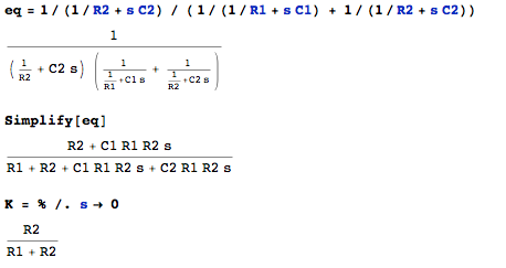
The answer given by the gentleman before is valid, but factor \$R_2\$ in the numerator \$R_2(1+sR_1C_1)\$, then \$s\$ in the denominator and then \$R_1+R_2\$. You obtain the same expression as in the above. This is a low-entropy form in which you see a dc gain (the leading term), a zero in the numerator and a pole in the denominator.
More details in the 2016 APEC presentation available here:
http://cbasso.pagesperso-orange.fr/Downloads/PPTs/Chris%20Basso%20APEC%20seminar%202016.pdf


