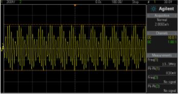
I have designed a transmitter and a receiver for amplitude modulation. Does the signal in the image looks like amplitude modulation?
-
\$\begingroup\$ Are the signal and the carrier wave separated by about a factor of 10? \$\endgroup\$– winnyCommented Sep 2, 2016 at 13:43
-
\$\begingroup\$ It certainly has an AM component. \$\endgroup\$– user16324Commented Sep 2, 2016 at 13:57
-
\$\begingroup\$ It would help to know what you are trying to achieve overall, and where in the process of modulating, transmitting, receiving, and detecting your trace is a snapshot of. \$\endgroup\$– Olin LathropCommented Sep 2, 2016 at 14:31
-
\$\begingroup\$ I am designing a 13.5 MHz transmitter. Both the transmitter and the receiver have antenna from a coil of wire. I just used copper wires around 5-6 turns.I used a function generator for generating the carrier signal. The snapshot is for modulating the data sent through a micro controller. \$\endgroup\$– el duderinoCommented Sep 2, 2016 at 16:54
2 Answers
Yes, there is some amplitude modulation. There is also a significant shift in the DC level of the carrier, seeming to correspond with the carried signal. In other words, this looks like amplitude modulation plus the baseband signal.
For most uses of amplitude modulation the additional baseband signal added to the carrier at the transmitter is irrelevant since it's at much lower frequency. It will get automatically filtered out by the resonant output filter of the transmitter, and the antenna system. Even if not, it should get filtered out by any competent receiver.
In your case, the modulating signal is only about 1/5 of the carrier frequency. If this signal is transmitted over the air, then that could result in significant out of band transmission, which may cause interference with other devices and be illegal.
If this is the signal inside your receiver, then it has problems. By the time you are trying to demodulate a AM carrier, it's DC level should be nice and constant. This is a basic assumption of most AM demodulation techniques, like the common diode detector.
As a side note, only 5:1 ratio of carrier to baseband signal is very slim. Depending on what the baseband signal is, it might result in unacceptably low signal to noise ratio. The spectrum of the whole AM signal will also be very broad relative to the carrier frequency. Usually you want significantly more frequency ratio for AM. That for commercial AM radio is about 100:1, for example.
The image you posted shows a constant-frequency carrier with a strong Amplitude Modulation at a frequency about 1/5-1/6 of the carrier frequency.
-
\$\begingroup\$ It's a tiny picture, but I'm counting only about 5 carrier cycles per envelope cycle. \$\endgroup\$ Commented Sep 2, 2016 at 14:24
-
\$\begingroup\$ I might have doubled the cycle there...messed up by drawing a +/- range around 2 pulses...thanks for catching that. \$\endgroup\$ Commented Sep 2, 2016 at 19:36

