4
\$\begingroup\$

Basically I am trying to send serial data from a Atmel to a string of ws2812 LEDs. I need to provide some isolation from the output pin to the LEDs located in a seperate place. My plan was to convert the data string to 12V and then back down at the LEDs in hopes of providing some noise immunity. WS2812 LEDs have their own 5V supply.

WHYThe environment is very electrically noisy and the atmel is on a good 5V supply and shielded along with a PLD that is controlling logic functions. The atmel only handles the lighting but is connected to many of the PLD inputs for data and a diagnostic function, but also on the same 5V supply. The main is 12V from a automotive type system. Very large loads are being switched on it. Transients of 8V to 30V are expected. Logic circuit is tested and everything else can handle the conditions.END_WHY

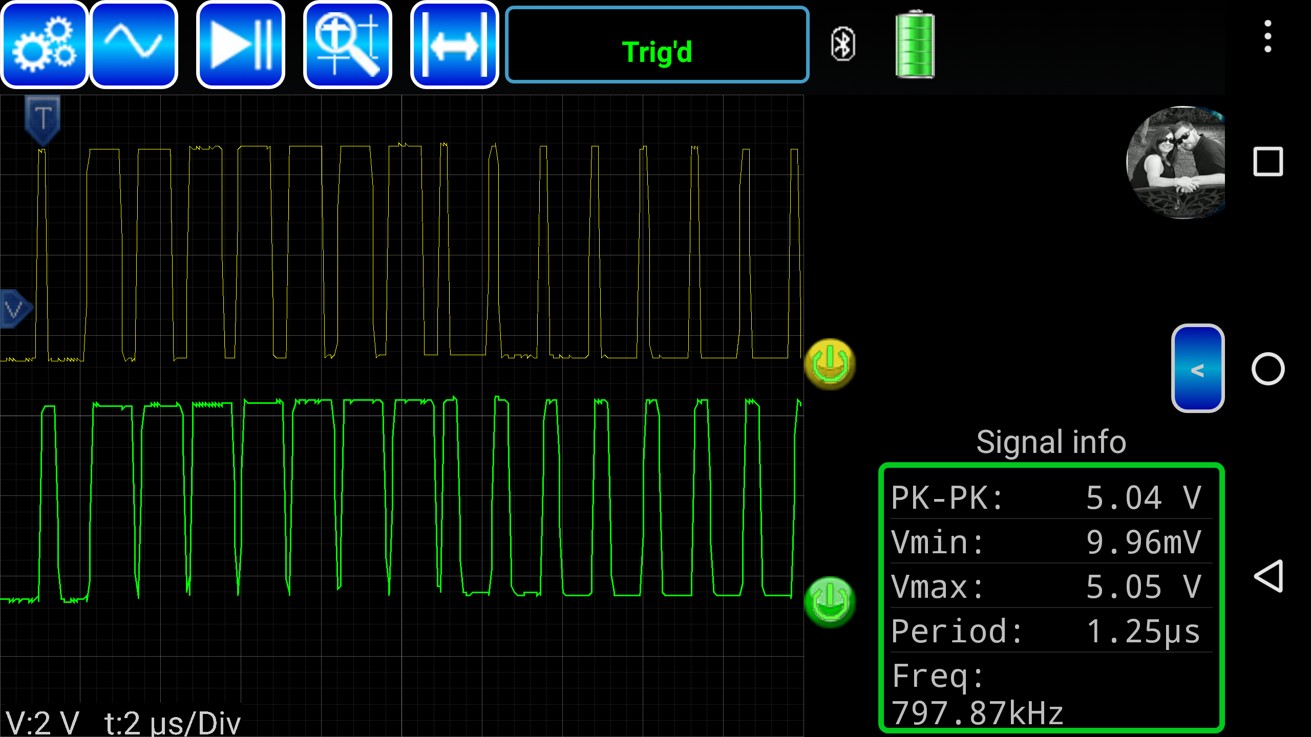
Originally I tried using 4n25 and 4n35 optos, but they don't switch nearly fast enough. The data string is 800Khz, which I didn't realize in the beginning, and uses a short pulse for a 0 and a long for a 1. Next I built a amp driving a 3904 with the atmel output and it drove a 3906, just like the attached circuit but with a 3904 instead of the 2n7000. I tried bypass caps and getting the transistors out of saturation, no luck there. The attached circuit works and I've played with values, but afraid I'm on the edge of it not working. I attached a screenshot of the scope output. So my questions are.

  1. Am I making a mistake turning the current back to a voltage for the LEDs with the resistors and zener(3.9V)

  2. What through hole opto can handle this? This is the preferred route since with an opto the whole 5V circuit can have an isolated ground. At least the transistors and mosfet should slow down anything nasty, maybe only blow the atmel.

  3. Is my mistake selecting a 3906 for this, or something else.

PS. I went to school for electronics and have lots of practical experience, just not in this area.

Thanks in advance for any input.
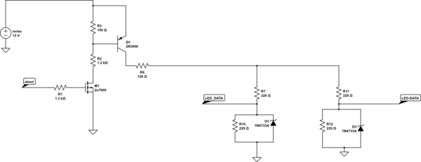
schematic

simulate this circuit – Schematic created using CircuitLab

enter image description here

\$\endgroup\$

1 Answer 1

1
\$\begingroup\$

MOSFETs might switch faster than BJTs. But to determine how far away you are from the edge, you have to find out where the edge is, i.e., increase the frequency or introduce more noise.

Anyway, that circuit has no isolation, and you are correct that you'd need a high-speed optocoupler for this. The H11L1 would be rated for 1 Mbit/s, but only for square signals, so it's probably beyond the edge. The 6N137 with 10 Mbit/s capability would work just fine.

The following circuit is stolen from the MIDI specification, and implements a 5 mA, active-low current loop:

current loop with 6N137

(The resistors R1..R3 are distributed this way to protect against short circuits at the cable's plugs; if you have a fixed connection, you might be able to combine them into a single resistor. The diode protects the 6N137's LED against reverse voltage; in a noisy environment, you probably still need it.)

\$\endgroup\$
3
  • \$\begingroup\$ Sorry but I'm a little confused. In my schematic the horizontal line coming off the 120ohm resistor is the signal line. My thinking that the the 3906 and the insulated gate of the 2n7000 provides more protection to MPU than the twisted lines. I looked at using the 6n137 to drive the gate of a MOSFET to switch the 12V on off like my circuit before. But I ran into the same problem I found before, that the output side is only rated for a 5V supply. \$\endgroup\$
    – Cory Lytle
    Commented Sep 4, 2016 at 1:58
  • \$\begingroup\$ A MOSFET's gate is much more vulnerable than a GPIO output (which connects almost directly to Vcc or GND), and having the 12 V and 5 V circuits connected directly is worse than being able to avoid the 12 V altogether. If you still have doubts, use a shielded cable, and add TVS diodes to the transmitter. \$\endgroup\$
    – CL.
    Commented Sep 4, 2016 at 8:01
  • \$\begingroup\$ Marked as answer. Still kinda feel like I'm hooking and antenna to my circuit. Thanks \$\endgroup\$
    – Cory Lytle
    Commented Sep 5, 2016 at 14:51

Your Answer

By clicking “Post Your Answer”, you agree to our terms of service and acknowledge you have read our privacy policy.

Not the answer you're looking for? Browse other questions tagged or ask your own question.