0
\$\begingroup\$

I have a voltage of 12v and I would like to get it down to around 8v. I know how voltage divider works and I already used it lots of times. But I ask you this: why cant I use only one resistor to drop the voltage in series with my circuit?

For example, suppose I have a motor with resistance 10ohm and I want to drop the voltage to 8v, why can I do this below?

  • (12V) -> RESISTOR -> MOTOR -> GND

I could easily calculate the voltage drop around the resistor so the remaining would be with the motor. Right?

\$\endgroup\$
3
  • \$\begingroup\$ A resistor divider is only usable for anything low current and your motor most probably isn't. Even just one resistor in series like you suggest will only drop the voltage down to 8 V for one particular current/motor load. Does your load vary? \$\endgroup\$
    – winny
    Commented Sep 18, 2016 at 13:54
  • \$\begingroup\$ You can as long as you know the current the motor will draw when turning. The measured resistance of the motor doesn't give you that, it will only give you the stall value. \$\endgroup\$ Commented Sep 18, 2016 at 13:54
  • \$\begingroup\$ This would work if you knew exactly what the load imposed by the motor was and it always stayed the same. You don't and it doesn't. If you measure the resistance of a motor as 10 ohms, that tells you its stall current at any voltage. If it's not stalled, its current reduces as it speeds up, and (thanks to your single resistance) the voltage across it increases... \$\endgroup\$
    – user16324
    Commented Sep 18, 2016 at 13:54

3 Answers 3

1
\$\begingroup\$

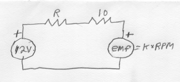
The motor is not just the resistance of the winding, it is the winding resistance in series with the back emf generated by the motor. You still have a voltage divider, but the voltage applied to the two resistors is the difference between the supply voltage and the back emf.

enter image description here

\$\endgroup\$
4
\$\begingroup\$

The problem is that the current drawn by the motor can vary significantly, so the voltage dropped by the resistor will vary significantly too (voltage across a resistor is proportional to the current thru it).

The motor may have a fixed DC resistance, but that does not imply that it always draws the same current when the same voltage is applied to it.

To first approximation, you can think of a motor as the DC resistance due to the windings in series with a ideal generator. As the motor spins due to applied voltage, that generator opposes the applied voltage. The voltage across the DC resistance, which the current is proportional to, is the applied voltage minus the generator voltage. When the motor is stalled, no internal voltage is generated, and the current is the applied voltage divided by the DC resistance. As the motor goes faster, the current goes down.

This is all a long-winded way to explain why just a resistor in series with a motor is not a good way to regulate the voltage applied to the motor.

Using a resistor in series to reduce the motor voltage is also inefficient, since the square of the current times the resistance is dissipated as heat. It is better to drive the motor with short pulses or full on and full off. You modulate the effective drive level by changing the fraction of the time the power voltage is applied. Just about any microcontroller can produce such a pulse train in hardware, with firmware only changing the on-time fraction, called the duty cycle.

\$\endgroup\$
1
  • \$\begingroup\$ Your explanation was the most complete and the better one but the one from Charles I think is easier to understand. \$\endgroup\$
    – Samul
    Commented Sep 18, 2016 at 15:06
-2
\$\begingroup\$

Actually this is a voltage divider what you described: 12v -> resistor -> motor -> GND where the motor has its resistance, the 12v is divided between the resistor and the motor. You can also calculate the voltage using the same equations.

However, for dividing the voltage as you described, you better use a MOSFET rather than a resistor.

\$\endgroup\$
2
  • \$\begingroup\$ (1) The motor does not present a constant resistance to the circuit. The back EMF will vary and the load current will vary. A simple series resistor may be adequate for certain limited applications but would generally not be a good solution. (2) Why should he use a MOSFET? What advantage would that give? \$\endgroup\$
    – Transistor
    Commented Sep 18, 2016 at 14:31
  • \$\begingroup\$ This does not answer the question. \$\endgroup\$
    – user98663
    Commented Sep 18, 2016 at 15:06

Your Answer

By clicking “Post Your Answer”, you agree to our terms of service and acknowledge you have read our privacy policy.

Not the answer you're looking for? Browse other questions tagged or ask your own question.