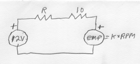
The problem is that the current drawn by the motor can vary significantly, so the voltage dropped by the resistor will vary significantly too (voltage across a resistor is proportional to the current thru it).
The motor may have a fixed DC resistance, but that does not imply that it always draws the same current when the same voltage is applied to it.
To first approximation, you can think of a motor as the DC resistance due to the windings in series with a ideal generator. As the motor spins due to applied voltage, that generator opposes the applied voltage. The voltage across the DC resistance, which the current is proportional to, is the applied voltage minus the generator voltage. When the motor is stalled, no internal voltage is generated, and the current is the applied voltage divided by the DC resistance. As the motor goes faster, the current goes down.
This is all a long-winded way to explain why just a resistor in series with a motor is not a good way to regulate the voltage applied to the motor.
Using a resistor in series to reduce the motor voltage is also inefficient, since the square of the current times the resistance is dissipated as heat. It is better to drive the motor with short pulses or full on and full off. You modulate the effective drive level by changing the fraction of the time the power voltage is applied. Just about any microcontroller can produce such a pulse train in hardware, with firmware only changing the on-time fraction, called the duty cycle.

