2
\$\begingroup\$

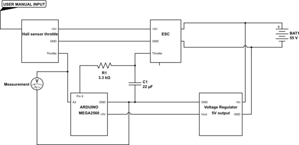
I have a hall sensor throttle which outputs a signal that scales between 0.8 and 3.6V. The problem is that when I connect it to an Arduino MEGA2560 analog input pin, the voltage never goes over 2.3V, either when measuring it with a multimeter or using the Serial port. It's like something in the Arduino limits the voltage to this value. What could this be due to and how can I solve it?

schematic

simulate this circuit – Schematic created using CircuitLab

The 2.3V are measured between the A2 pin on the Arduino and the throttle

\$\endgroup\$
2
  • 5
    \$\begingroup\$ You are not giving us many clues to help you. (1) Schematic. (2) Datasheet for throttle. (3) Configuration of analog input in code. Please edit your question. \$\endgroup\$
    – Transistor
    Commented Oct 5, 2016 at 17:28
  • \$\begingroup\$ Sorry about that, just edited my question. I have very limited information regarding the throttle apart from the fact that it is a Hall sensor throttle and the range of the output signal it produces. The input pin is simply initialised as: pinMode(A2, INPUT);//Throttle in \$\endgroup\$
    – Eliott W
    Commented Oct 5, 2016 at 18:09

2 Answers 2

3
\$\begingroup\$

As we can read in the datasheet:

The ADC is optimized for analog signals with an output impedance of approximately 10k or less. If such a source is used, the sampling time will be negligible. If a source with higher impedance is used, the sampling time will depend on how long time the source needs to charge the S/H capacitor, which can vary widely. The user is recom- mended to only use low impedant sources with slowly varying signals, since this minimizes the required charge transfer to the S/H capacitor.

If this is a case of impedance mismatch, then you need some kind of impedance buffer.

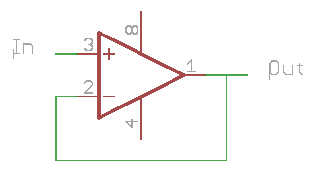
One of the possible solutions could be an op-amp in "voltage follower" configuration. enter image description here

http://www.atmel.com/Images/Atmel-2549-8-bit-AVR-Microcontroller-ATmega640-1280-1281-2560-2561_datasheet.pdf

\$\endgroup\$
3
\$\begingroup\$

I think something in your setup is not configured or behaving as you are expecting.

If you measure the signal with a multimeter without it connected to the Arduino does the signal go above 2.3 V?

If it does not go above 2.3 V then this has nothing to do with the Arduino, or the signal may only be going above 2.3 V for very short periods of time and you are simply not sampling fast enough to see these events. (sampling in a loop while outputting information to the serial monitor is not very fast and multimeters are not designed to capture high frequency information)

If you are sure the signal should be going above 2.3 V then I might suspect the latter to be happening. To get a better understanding you may want to look at the signal with a digital oscilloscope that can capture higher frequency waveforms.

If it does go above 2.3 V when not connected to the Arduino then it seems that there is some interaction with your signal and the ADC input resistance. The ADC input resistance is specked at 100 M\$\Omega\$, so this seems unlikely but could happen.

http://www.atmel.com/Images/Atmel-2549-8-bit-AVR-Microcontroller-ATmega640-1280-1281-2560-2561_datasheet.pdf

EDIT:

After reading your comment it seems that you have set the analog input up as a digital input which will not behave as you expected. You only need to set the pinmode for digital pins. To read the voltage simply remove the pinMode(A2, INPUT); line of your code and when you wish to read the analog value just use analogRead(A2);

https://www.arduino.cc/en/Reference/PinMode

https://www.arduino.cc/en/Reference/AnalogRead
\$\endgroup\$
3
  • \$\begingroup\$ When I measure the signal with a multimeter without it connected to the arduino, the signal does go above 2.3V and is operational on its full range (0.8 to 3.6V). \$\endgroup\$
    – Eliott W
    Commented Oct 6, 2016 at 11:08
  • \$\begingroup\$ Did you try changing the code as I suggested? \$\endgroup\$
    – rtclark
    Commented Oct 6, 2016 at 12:53
  • 1
    \$\begingroup\$ Yes, thank you but the problem was wimply that i was underpowering the arduino, feeding only 5V to the board! \$\endgroup\$
    – Eliott W
    Commented Oct 9, 2016 at 17:03

Your Answer

By clicking “Post Your Answer”, you agree to our terms of service and acknowledge you have read our privacy policy.

Not the answer you're looking for? Browse other questions tagged or ask your own question.