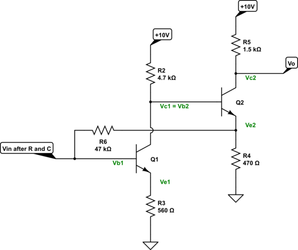
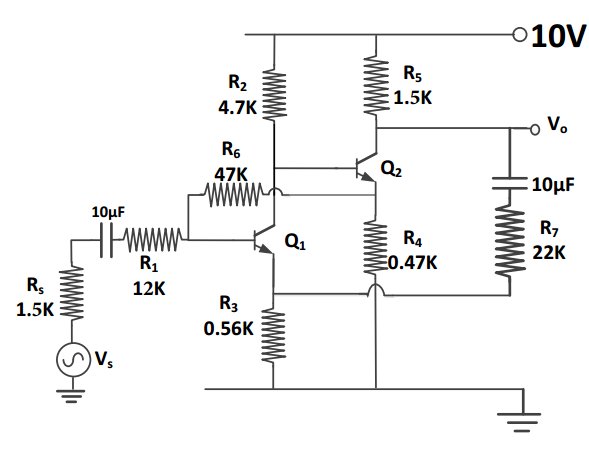
Let me start things out by looking only at the DC operating point. You'll see some problems that may be present, then. This circuit's behavior has some overly strong dependencies on \$\beta\$.

simulate this circuit – Schematic created using CircuitLab
I get the following:
$$\begin{align*}
I_{B_1} &= \frac{V_{E_2}-V_{BE_1}}{R_6 + \left(\beta_1+1\right)\cdot R_3} \\
\\
I_{C_1} &= \beta\cdot I_{B_1}\\
\\
V_{C_1} &= V_{B_2} = V_{CC} - R_2\cdot I_{C_1} \\
\\
V_{E_2} &= V_{B_2} - V_{BE_2}
\end{align*}$$
At this point, it's possible to solve for \$V_{E_2}\$:
$$\begin{align*}
V_{E_2} &= V_{B_2} - V_{BE_2} \\
\\
&= V_{CC} - R_2\cdot I_{C_1} - V_{BE_2} \\
\\
&= V_{CC} - R_2\cdot \beta_1\cdot I_{B_1} - V_{BE_2} \\
\\
&= V_{CC} - R_2\cdot \beta_1\cdot \frac{V_{E_2}-V_{BE_1}}{R_6 + \left(\beta_1+1\right)\cdot R_3} - V_{BE_2} \\
\therefore \\
V_{E_2} &= \frac{\left(V_{CC}-V_{BE_2}\right)\cdot\left(R_6 + \left(\beta_1+1\right)R_3\right)+\beta_1 R_2 V_{BE_1}}{R_6 + \beta_1 R_2 + \left(\beta_1+1\right)R_3}
\end{align*}$$
Assuming \$\beta_1=100\$, \$\beta_2=100\$, \$V_{BE_1}=680\:\textrm{mV}\$, and \$V_{BE_2}=700\:\textrm{mV}\$, then \$V_{E_2}\approx 2.236\:\textrm{V}\$. From there, we find that \$I_{C_1}\approx 1.5\:\textrm{mA}\$, \$I_{C_2}\approx 4.7\:\textrm{mA}\$, \$V_{C_1}\approx 3\:\textrm{V}\$, \$V_{CE_1}\approx 2.1\:\textrm{V}\$, \$V_{C_2}\approx 3\:\textrm{V}\$, and \$V_{CE_2}\approx 700\:\textrm{mV}\$. The first stage has a little bit of working room; perhaps \$V_{pk}=1-1.5\:\textrm{V}\$ with a positive going input swing at \$V_{IN}\$. But the second stage is already crossing over into saturation and has no room to work, at all, for a negative going input swing at \$V_{IN}\$. I consider this to be an essentially useless state of affairs.
Assuming \$\beta_1=200\$, \$\beta_2=200\$, \$V_{BE_1}=680\:\textrm{mV}\$, and \$V_{BE_2}=700\:\textrm{mV}\$, then \$V_{E_2}\approx 1.931\:\textrm{V}\$. From there, we find that \$I_{C_1}\approx 1.57\:\textrm{mA}\$, \$I_{C_2}\approx 4.1\:\textrm{mA}\$, \$V_{C_1}\approx 2.7\:\textrm{V}\$, \$V_{CE_1}\approx 1.8\:\textrm{V}\$, \$V_{C_2}\approx 3.9\:\textrm{V}\$, and \$V_{CE_2}\approx 2\:\textrm{V}\$. The first stage still has a little bit of working room, though less; perhaps \$V_{pk}=1\:\textrm{V}\$ with a positive going input swing at \$V_{IN}\$. And luckily now, the second stage has a little room left for a negative going input swing at \$V_{IN}\$, too. But again on the order of \$V_{pk}=1\:\textrm{V}\$, but as the gain is about 3 this means that the first stage can't present more than about \$300\:\textrm{mV}\$ in that direction. So this means the first stage is thus actually limited to an output swing of \$\pm 300\textrm{mV}\$ or an input swing of about \$\pm 35\textrm{mV}\$ (before we take into account the negative feedback from \$R_6\$.) This isn't entirely useless.
The above exposes some questions about the DC operating point that was chosen and its sensitivity to \$\beta\$. Depending on the actual value, the circuit goes from limited utility to useless.
Now, it's clear that \$R_6\$ is providing DC bias for stage 1. But it is also providing negative feedback, since \$Q_2\$'s emitter follows the signal at \$Q_1\$'s collector which itself is an inverted copy, with gain, of the input signal. (Ignoring limitations noted above about the DC operating point.)
You may want to compute this local negative feedback's \$B_1\$ value (a value from 0 to 1, we expect to apply in your open-loop to closed-loop equation) before taking on what \$R_7\$ then does. Roughly speaking, you want to compute this as:
$$B_1=\frac{\textrm{d}V_{B_1}}{\textrm{d}V_{E_2}}$$
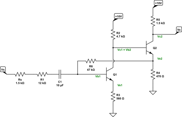
But to get that, you need to take into account what is happening at the input node. You actually have three sources and impedances all vying for it. The input signal through its impedance, the emitter resistance via \$\beta_1\$ to ground, and \$V_{E_2}\$ through \$R_6\$. Let's add that to the schematic now:

simulate this circuit
The equation to compute the voltage there, just cobbled up as a DC equation for now and ignoring the impedance of the \$10\:\mu\textrm{F}\$ input capacitor, would be:
$$\begin{align*}
V_{B_1}&=\frac{V_s \beta_1 R_3 R_6+V_{E_2}\beta_1 R_3\left(R_s+R_1\right)}{\beta_1 R_3 R_6 + \beta R_3 \left(R_s+R_1\right) + R_6 \left(R_s+R_1\right)} \\
\\
&=\frac{V_s R_6+V_{E_2}\left(R_s+R_1\right)}{R_6 + R_s+R_1 + \cfrac{R_6 \left(R_s+R_1\right)}{\beta_1 R_3}}
\end{align*}$$
Holding \$V_s\$ constant, we can now compute \$B_1\$ as:
$$B_1=\frac{R_s+R_1}{R_6 + R_s+R_1 + \cfrac{R_6 \left(R_s+R_1\right)}{\beta_1 R_3}}$$
For \$\beta_1=100\$, this works out to \$B_1\approx .188\$. For \$\beta_1=200\$, this works out to \$B_1\approx .204\$.
Given your equation that takes the open-loop gain for the first stage as \$A\approx \frac{4.7\:\textrm{k}\Omega}{4.7\:\textrm{k}\Omega} \approx 8.3 \$, then it follows that for \$\beta_1=100\$ that \$A_{closed}\approx 3.2\$ and for \$\beta_1=200\$ that \$A_{closed}\approx 3\$. So the closed loop gain on the first stage is about 3, taking into account \$R_6\$ (which serves both as a biasing resistor and as a negative feedback.)
However, that figure still doesn't take into account the fact that the input source is, itself, loaded down by the first stage's input impedance. That input impedance works out to about:
$$\begin{align*}\frac{\left(\beta_1+1\right) R_3 R_6}{R_6 + \left(\beta_1+1\right) R_3} \approx 33\:\textrm{k}\Omega
\end{align*}$$
Taking that into account with the input impedance, you'd get about:
$$\begin{align*}\frac{33\:\textrm{k}\Omega}{33\:\textrm{k}\Omega + 13.5\:\textrm{k}\Omega} \approx .7
\end{align*}$$
So from input signal to output of stage 1, including the input loading and negative feedback from \$R_6\$, I figure a total gain at the output of stage 1 of about 2.1.
I'm leaving the last step for you, where you include the impact of \$R_7\$.


