2
\$\begingroup\$

I'm currently working on a project which uses an LED and a photoresistor to work out my BPM.

I have a schematic which I've built into a prototype which all works fine and when I run the serial monitor in Arduino I'm getting output values.

The problem is, when I place a finger in between the LED and photoresistor, for some reason the readings are going to 0 and I'm unsure why?

I've encased with led and photoresistor to avoid any other light but for some reason I'm not getting any values.

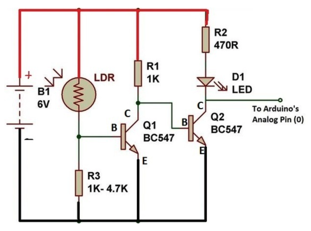
Here is the schematic that i'm following: Here is the schematic I'm using

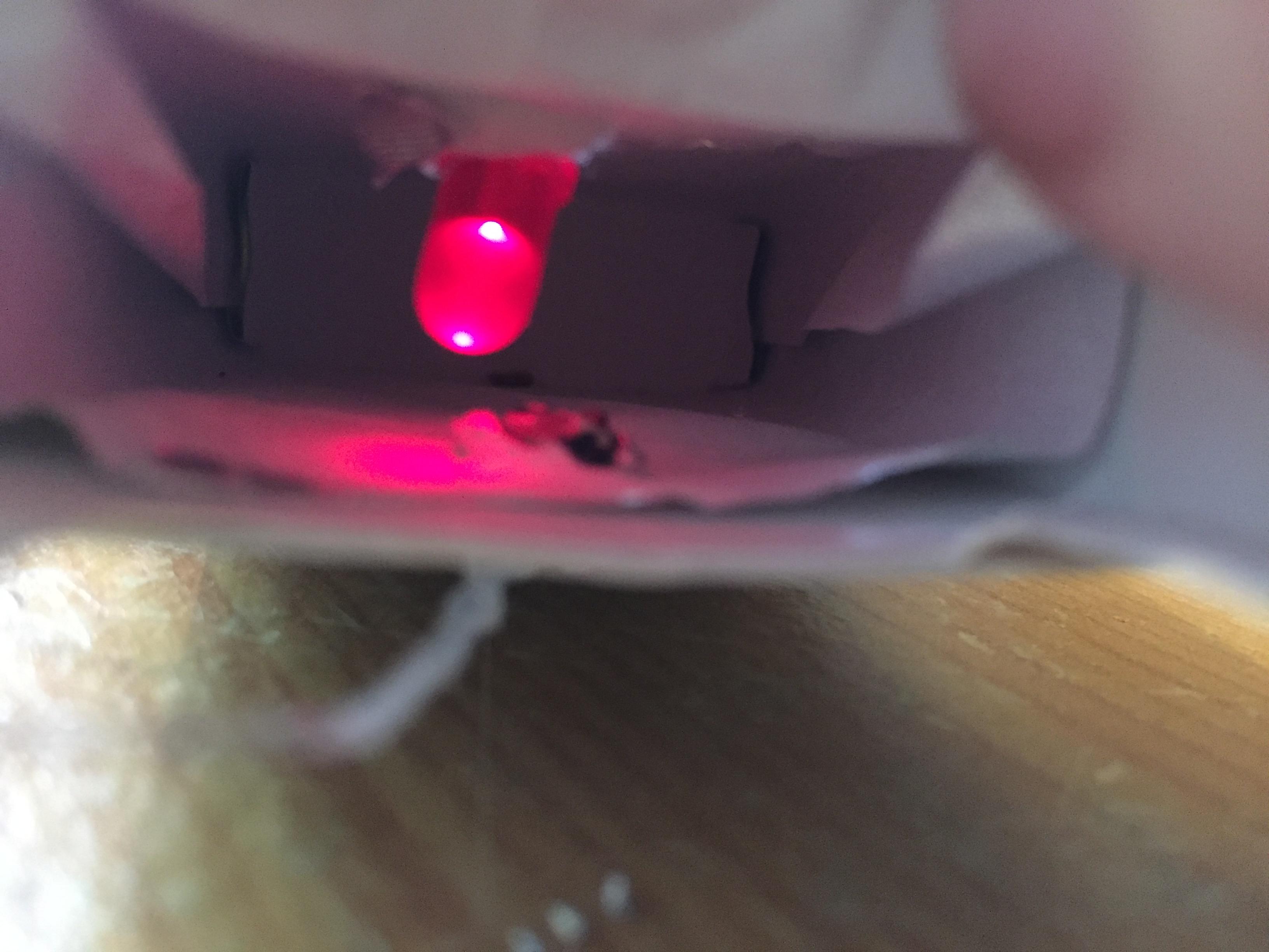
You'll have to excuse my choice of encasement: enter image description here

Unsure of what reasons which could be preventing the LDR of outputting.

\$\endgroup\$
8
  • 1
    \$\begingroup\$ So you are blocking the light from the LDR and wonder why it is not detecting any light? \$\endgroup\$
    – PlasmaHH
    Commented Oct 17, 2016 at 11:07
  • \$\begingroup\$ I thought thats how pulse oximetry works? The LDR detects IR light \$\endgroup\$
    – F. Bar
    Commented Oct 17, 2016 at 11:08
  • 1
    \$\begingroup\$ R3 is probably much too small. What's the resistance of the LDR in darkness? \$\endgroup\$
    – JimmyB
    Commented Oct 17, 2016 at 15:35
  • \$\begingroup\$ Yes, but you're not thinking about this very well. You seem to indicate that there is an output when the LDR is illuminated, and none when it's not. In other words, the LDR is operating exactly as it should. Why do you think that the circuit should have an output when the LED is blocked? If there were an output in both cases, you wouldn't be able to distinguish between them, and what's the point of that? \$\endgroup\$ Commented Oct 17, 2016 at 15:37
  • 1
    \$\begingroup\$ @WhatRoughBeast The OP writes "to work out my BPM" - Which I interpret as the attempt to build a heart rate monitor (Beats Per Minute). \$\endgroup\$
    – JimmyB
    Commented Oct 17, 2016 at 15:40

3 Answers 3

2
\$\begingroup\$

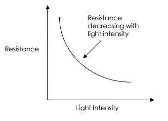
The situation is simple. If you make it impossible for light to enter the LDR then the resistance of that device is increasing as you can see from the added picture.

enter image description here Removing the light with your finger makes the resistance go up. The result is that the base of Q1 does not receive enough current anymore to make it conduct. The collector of Q1 goes up and Q2 starts to conduct in full. So the led D! starts to glow.

The next step is to understand what happens when the led is putting it's light on the LDR.

Looking at the schematic again you can see that if Q1 starts to conduct complete Q2 will be cut of and the led goes off. However that is not possible because then there is no light falling on the LDR anymore.

The result will be a balance whereby the resistance of the LDR lowers enough with the light from the LED to keep Q1 and Q2 conducting so much that the light from the led is sufficiant to keep the LDR at the resistance needed.

Now if you start playing with this combination then you are able to change the balance and send the resulting signal to the analog input of arduino.

\$\endgroup\$
0
\$\begingroup\$

As far as I can tell, you've been receiving a lot of misinformation since a pulse oximeter relies on two different wavelengths of light and a phototransistor in order to work, so with a single IR emitter - even though you've shown visible light as your source - neither the scheme with the single emitter or the scheme with the LDR will work.

Here's a pretty good rundown of how it all fits together:

https://en.wikipedia.org/wiki/Pulse_oximetry

\$\endgroup\$
9
  • \$\begingroup\$ I've just checked out that and have been reading up on the proper way to do it. Do you think actually building a circuit and writing the code for proper way is feasible as a third year project? \$\endgroup\$
    – F. Bar
    Commented Oct 17, 2016 at 23:16
  • \$\begingroup\$ Unless you've convinced yourself otherwise, why not? \$\endgroup\$
    – EM Fields
    Commented Oct 18, 2016 at 0:05
  • 1
    \$\begingroup\$ You can probably see pulse with one color. The second color is to help differentiate deoxyhemoglobin from oxyhemoglobin. \$\endgroup\$ Commented Oct 18, 2016 at 0:20
  • \$\begingroup\$ Though I wouldn't expect an LDR to be sensitive enough \$\endgroup\$ Commented Oct 18, 2016 at 0:20
  • 2
    \$\begingroup\$ You're looking for very small changes in light level, and LDRs are not as sensitive as photodiodes. Plus, they're slow. Wouldn't be my first choice, given the easy availability of photodides. \$\endgroup\$ Commented Oct 18, 2016 at 0:44
0
\$\begingroup\$

Seems to me that with that circuit as it stands you have inadvertently built an oscillator whose frequency is determined by the stray capacitances in the circuit. That it probably doesn't work even as an oscillator is because LDRs are slow, comparatively speaking, at following changes in light level.

EDITED: Due to my intense curiosity and lingering doubts about the schematic you are/were working with, I did some research. While this reply is perhaps a year too late for your proposed project, here are some pieces of advice should you still be interested: Please heed the advice of October 2016 from poster EM Fields. Also, read this reference International Journal of Latest Research in Science and Technology ISSN (Online):2278-5299 Volume 3, Issue 5: Page No 148-152. September-October 2014 It is available as pdf download http://www.mnkjournals.com/ijlrst_files/Download/Vol%203%20%20issue%205/27-31-20102014%20An%20Overview%20On%20Heart%20Rate%20Monitoring%20And%20Pulse%20Oximeter%20System.pdf

And sorry, I did try to put the above site into a link, but as I see it on my computer, I failed in that task.

The website and the journal entry will demonstrate how your circuit as presented can never work as you intend for a number of reasons that will ( or "will have") become clear to you, as you include those sources to the others you have been offered in your ongoing research. Definitely abandon any development of your present oximeter circuit until you have both read what posters have given your here, and also probably more importantly, acquaint yourself with the parameters of components you plan to use and these include spectral sensitivities, speed of operation and knowledge of filters at visible and IR light frequencies.
\$\endgroup\$

Your Answer

By clicking “Post Your Answer”, you agree to our terms of service and acknowledge you have read our privacy policy.

Not the answer you're looking for? Browse other questions tagged or ask your own question.