0
\$\begingroup\$

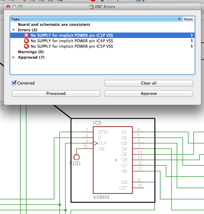
I'm currently building an Arduino based LED driver using a set of three CD4094's, I'm slightly unsure of an error I'm getting with my Eagle schematic. The error message reads: 'No SUPPLY for implicit POWER pin ICP3 VSS' - however I can't see which pin I'm supposed to attach VSS to? Here's my pinout:

http://edcs.me/files/2012/02/Screen-Shot-2012-02-04-at-21.28.19.png

Is this just an erroneous message or have I made a mistake? When I've seen schematics with this IC used before, they have used the same pin mapping as I've used...

\$\endgroup\$
0

1 Answer 1

1
\$\begingroup\$

That's an Eagle oddity called "Implicit Power Pins". Someone thought that it was onerous to wire Vcc and Vss pins to every gate, so they came up with this solution.

As the error message suggests, there's an implicit power pin for Vss. Select the part, and then issue the invoke command. You'll be presented with a simple pin symbol which you can drop anywhere on your schematic. Even thought the schematic symbols are distinct, they're mapped to the same physical part.

Alternatively, the Eagle way is to wire it up by creating a net called "Vss" somewhere in your schematic, perhaps on a decoupling cap. This is automatically connected to all the implicit Vss pins on any ICs which use this mechanism. Use the appropriate power pins in the 'supply' library to make this connection.


Personally, I edit symbols which are built like this. Open a library you want your fixed part to go into. Then, in the control window, open the library containing this part, and right-click -> 'copy to library'. Edit the symbol to include power and ground pins, and edit the part to use these new pins over the implicit ones.
\$\endgroup\$
2
  • \$\begingroup\$ Thanks for your help! I found the invoke function and have added the extra symbol to my schematic, however it's raised another question - I don't think my power supply circuit is configured correctly. I've added VDD, VCC and VSS as per the original schematic I'm working off goes, but it doesn't seem right to me and it causes mixed signal errors in Eagle: edcs.me/files/2012/02/Screen-Shot-2012-02-05-at-08.57.26.png \$\endgroup\$
    – edcs
    Commented Feb 5, 2012 at 9:07
  • \$\begingroup\$ Yeah, you can't connect Vcc to Vdd. The concept is that they're different nets; you similarly can't connect +5V and +12V. You should choose what name you're going to use for each and just use one. I usually use +5V, +12V, and GND. Of course, symbols which require you to use a certain name make this rather difficult. It looks like the stock 4094N requires Vdd and Vss, you'll have to replace all of the GND nodes with Vss and all of the +5V and Vcc nodes with Vdd. \$\endgroup\$ Commented Feb 6, 2012 at 16:15

Your Answer

By clicking “Post Your Answer”, you agree to our terms of service and acknowledge you have read our privacy policy.

Not the answer you're looking for? Browse other questions tagged or ask your own question.