6
\$\begingroup\$

I'm trying to make a zero cross detector. I used the schematic below as a reference.(schematic from http://microcontrollerslab.com/zero-crossing-detector-circuit-using-pic-microcontroller/)

enter image description here

However if I hook up my scope then I get the following image:

enter image description here

You can see that ther is only 1 zero cross detected while there should be 2. Can someone explain why this happens?

I am using 1n4007 diodes and a bc547 npn transistor.

When a 10kOhm resistor is applied at the output of the bridged rectifier: enter image description here

Many thanks in advance.

\$\endgroup\$
8
  • 2
    \$\begingroup\$ Try putting 10 kohm to 100 kohm across output of bridge rectifier. \$\endgroup\$
    – Andy aka
    Commented Nov 15, 2016 at 15:58
  • 1
    \$\begingroup\$ very poor design. see my suggestion and add filter and TVS protection to divider. You ought to consider what happens? if the line has a 3kV 10us pulse , what impedance is the input, how importance is the stability of the clock with a brown out? the diode bridge is also an XOR gate but poorly terminated \$\endgroup\$
    – D.A.S.
    Commented Nov 15, 2016 at 19:20
  • 1
    \$\begingroup\$ @TonyStewart.EEsince'75, I'm afraid that I don't completely understand you. Do you have a schematic or an article or such about your suggestion? \$\endgroup\$
    – ChThy
    Commented Nov 15, 2016 at 19:37
  • 1
    \$\begingroup\$ no, this is common knowledge. ask a question, or be specific about how accurate you want ZCS pulse.. and follow the XOR method. voltage divider, ~1kHz LPF > 1Hz HPF> 3Vpp sine into CMOS gate with 1M feedback> XOR gate both inputs except one side 10kHz LPF to produce 100us pulse out. \$\endgroup\$
    – D.A.S.
    Commented Nov 15, 2016 at 19:39
  • 1
    \$\begingroup\$ @TonyStewart.EEsince'75: I'm sorry but this is not common knowledge for me. I'm just an electronic hobbyist. So if I'm getting right what you suggest, you would place a 20:1 voltage divider on the AC signal. Then place a LPF followed by a HPF? \$\endgroup\$
    – ChThy
    Commented Nov 15, 2016 at 20:30

4 Answers 4

8
\$\begingroup\$

The basic problem is that your AC source is not-isolated from ground. If it were then there would be no problem when you add the 10 kohm resistor that I recommended.

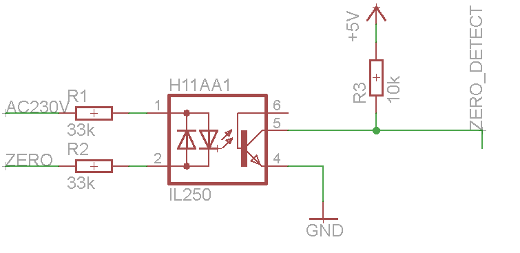
So, you have one incoming AC line close to earth potential and on the DC side of the bridge you are connecting one side down to earth and this turns the full wave rectifier into a half wave rectifier and you are just seeing the rectified positive half cycles when the non-earthed AC line rises positively.

This circuit only will work when there is galvanic isolation between input AC and earth. I would also recommend that you need isolation for safety reasons so, maybe use an opto-isolator solution. Here are a couple of ideas: -

enter image description here

enter image description here

\$\endgroup\$
3
  • 5
    \$\begingroup\$ +1 For promoting opto isolation. The unisolated voltage and zerocrossing detectors are a accident waiting to happen in all cases when the complete circuit is NOT totally independant and isolated from everything else. Any other PSU, scope, laptop, person may cause ground faults of various sizes. \$\endgroup\$
    – KalleMP
    Commented Nov 15, 2016 at 19:49
  • \$\begingroup\$ The top circuit will produce glitches at the peaks, not the zero crossings. \$\endgroup\$ Commented Nov 15, 2016 at 23:17
  • \$\begingroup\$ @OlinLathrop yes, because of those capacitors. Thanks I shall fix this. \$\endgroup\$
    – Andy aka
    Commented Nov 16, 2016 at 8:17
2
\$\begingroup\$

The missing pulse is due to insufficient Dc load and some stray effects.

Put a load R of 22k to 47k or so across the Dc side of bridge. to make a 20:1 divider. Without this when the transistor base of off, there is no resistance but some stray capacitance. If you intend to power off same bridge adding a cap will cause both pulses to be missed, then you need a different circuit. see link below.

A better way is ac couple a reduced voltage to 3Vpp and drive a self biased gate to make a square wave then use an XOR with delay on one side to produce the pulse for each crossing at any width you need with RC delayed clock compared with clock to get _ | _ | _ | _ | _

enter image description here

https://sound-au.com/appnotes/an005-f1.gif

for other ways to do ZCS pulse, some ok, some not https://www.bing.com/images/search?q=zero+crossing+detector&PC=CMPF&FORM=PUFDEF

\$\endgroup\$
2
  • \$\begingroup\$ See the answer refering to lack of isolation between sensing circuit and mains circuit, be careful. \$\endgroup\$
    – KalleMP
    Commented Nov 15, 2016 at 19:50
  • \$\begingroup\$ When I was a recent grad , I built an 8 channel triac chaser using similar ZCS methods and offline power in a double insulated box for a rock band. circa '75 If user is not aware, then they must become aware to read how to use grid before sticking scope probes on logic grounds shown in these schematics and cause their new DSO to go poof. We can give caution but not teach them how to be cautious. \$\endgroup\$
    – D.A.S.
    Commented Nov 15, 2016 at 19:59
1
\$\begingroup\$

You have nothing actively driving the base of Q1 low during the rather short time the full wave bridge output is near zero. Even stray capacitance on the rectified signal apparently keeps it high long enough so that the transistor doesn't turn off.

To fix this, add a resistor between the base and emitter of Q1. It's not clear what voltage is coming out of BR1, but 10 kΩ B-E will probably do it. That not only will actively turn off the transistor a little, but is also increases the threshold of the BR1 output signal where it is considered "zero".

Added

You have added a 10 kΩ resistor on the output of BR1. Now the zero detect signal is more of a square wave.

Looking at the BR1 output signal we can see why, which is that one of the two half-cycles is missing. This means at least one of the diodes that should conduct that half-cycle is open. Since the four diodes are integrated into a single unit, you have to replace the full wave bridge. If you don't have another one, then you can make one from four diodes. Make sure they are rated for the full peak to peak AC voltage, plus some margin.

Another possibility is that the AC source you show is not really floating as you show. If it is the power line, then it is ground-referenced. That's not going to work as you seem to intend if your circuit is also ground-referenced.

Pop up a couple of levels and define the real problem. Right now we're trying to bandaid what seems to be a basically flawed implementation. Explain what this AC source is, how close to the zero crossing you need a pulse edge, etc. Since this appears to just be going into a micro, I don't see the need for a pulse at the zero crossings. A edge would be easier to make, and just as easy to handle with slightly different firmware.

\$\endgroup\$
3
  • \$\begingroup\$ So i added a 10 k resistor and I got a completely other image. I added the image at the end of the original post. Can you take a look at it please? \$\endgroup\$
    – ChThy
    Commented Nov 15, 2016 at 17:10
  • \$\begingroup\$ The AC source is the power. I live in Belgium where the AC is 230 V (Ueff) with a 50 Hz frequency. I want the zero crossing as close as possible since I want to make an AC controller. \$\endgroup\$
    – ChThy
    Commented Nov 15, 2016 at 18:49
  • 1
    \$\begingroup\$ @mai: In that case I'd use two parallel opto-isolators that produce a square wave. The edges will be close to the AC line zero crossings. You are running into trouble, and safety issues, but directly connecting the controller and the AC line. \$\endgroup\$ Commented Nov 15, 2016 at 19:36
0
\$\begingroup\$

Am a bit surprised that such a low-frequency source doesn't discharge Q1's base-emitter capacitance at the zero-crossing points. The 1N4007 diodes also have significant capacitance that must be discharged. A large value resistor like 500k from base-to-ground should improve response.
Your AC source is line frequency perhaps? If it is a low-impedance source, those 220K series resistors (R3,R5) could be reduced in value a great deal - but if your AC source is line-voltage (220v or 120v RMS) then R3,R5 shouldn't be reduced to small values. Expect that the collector pulse width will be broader in time with the base-to-ground resistor.
If you try this circuit at higher frequency, resistor value will have to be even lower to get Q1 off at zero crossing.
These changes make response-time faster, so you become susceptible to glitches, where a noise spike from your source is counted as a zero crossing. So don't go overboard in speeding things up.

\$\endgroup\$
2
  • \$\begingroup\$ That's a zero crossing circuit for line (probably 110VAC) voltage. Reducing the 220k resistors is probably not a good idea. \$\endgroup\$
    – JRE
    Commented Nov 15, 2016 at 16:11
  • \$\begingroup\$ @JRE Good point - safety first. In that case, Q1 is very susceptible to static/lightning discharges. Large resistors certainly help. \$\endgroup\$
    – glen_geek
    Commented Nov 15, 2016 at 16:15

Your Answer

By clicking “Post Your Answer”, you agree to our terms of service and acknowledge you have read our privacy policy.

Not the answer you're looking for? Browse other questions tagged or ask your own question.