4
\$\begingroup\$

I am really in a tough situation and need very serious elaborative help with this. Almost like spoon-feeding.

It's been days I've been trying to get my zero cross detector (and the triac dimmer) to work properly but nothing works fine. I am trying to get my circuit to work but all in vain whereas there is another product (which I opened to reverse engineer) that uses the same triac and almost similar components but with few changes and sill works. I'll explain both cases to you.

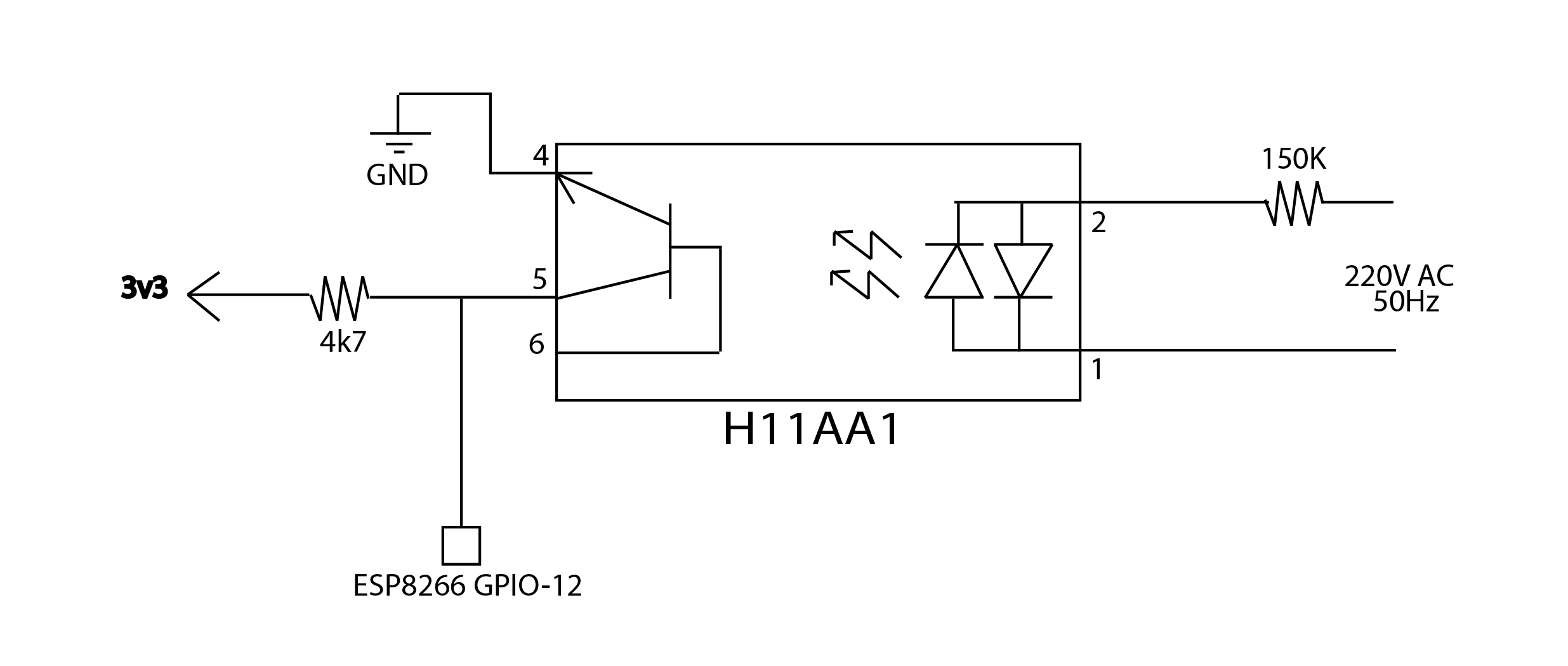
I am using an H11AA1 optocoupler with a 150k resistor to use AC voltage to generate interrupts on my ESP8266 (esp-12e) micro-controller (integrated wifi). The circuit is as in image

enter image description here

But the problems that I face a numerous -

  • A 1/4W resistor gets too hot and burns if any lesser value is used.
  • The interrupts are for the RISING edge as there will be spikes when there is zero cross. The interrupt durations are (in milliseconds) are like -- 10,9,0,0,1,9,10,0,0,0,10,0,0,10,9,9,1,0,0,1,1,10,....... and so on. WHY?!!? Why is it so jumpy? And the random values? I was suggested that the current on the AC side is less. But as I said lowering resistance burns it and increasing might spoil it more. Talk about paradox, huh?

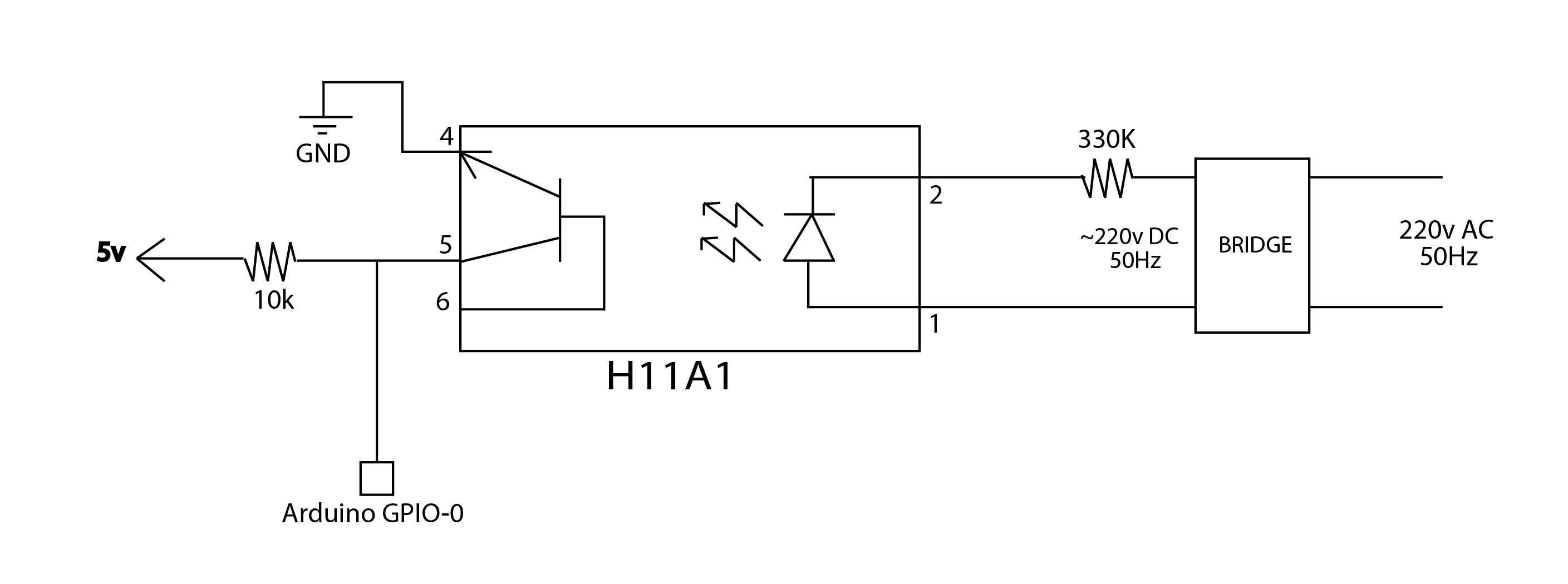
Now about the product I was trying to reverse engineer -

enter image description here

Why that's a problem to me -

  • They are using a variant of the (almost) same opto-coupler, H11A1. And they use a "330k" smd resistor (x2 times higher) that's got to be 1/4W. Now obviously the 2 times higher resistance is the reason why it's not burning. But how's that giving enough current to generate the right interrupts?

Please help me here. With the current scenario there's pretty irregular flickering in the triac dimmer tested with incandescent light bulb. It's been days to understand why this is happening...

Big thanks in advance.. :)

\$\endgroup\$
9
  • \$\begingroup\$ 1. 150k * 10 != 330k. 2. A product does not end at the IO pin. 3. Trigger levels of an Atmel on 5V and an ESPxxxx on 3.3V will not be the same. 4. For any real useful help add links to the Datasheets of the stuff you are using. \$\endgroup\$
    – Asmyldof
    Commented Apr 7, 2016 at 23:38
  • 3
    \$\begingroup\$ small resistors have breakdown voltages that can be easily exceeded by mains voltage, I'd use more than one resistor in series for safety and durability.. \$\endgroup\$
    – Wesley Lee
    Commented Apr 7, 2016 at 23:48
  • \$\begingroup\$ Do you really want 220 Vac going into the opto coupler? A nice step down transformer, say to 24Vac would make it safe, and not burn up resistors. \$\endgroup\$ Commented Apr 8, 2016 at 1:42
  • \$\begingroup\$ Asmyldof - thanks for pointing that out. I wrote 10 times as I was experimenting with 33k at the moment of posting question. I edited it now. PS - 33k smoked up instantly. \$\endgroup\$ Commented Apr 8, 2016 at 7:14
  • \$\begingroup\$ Are you using nodemcu firmware on your esp8266? if yes. that explains the flickering in your interrupts durations..and now for the circuit.. I am using a circuit based on 4n35 which works like a charm for me.. if you're interested I would love to explain this. \$\endgroup\$ Commented Apr 9, 2016 at 16:55

2 Answers 2

2
\$\begingroup\$

Resistor

A 150kΩ resistor on 220Vac is dissipating 0.32W and probably should be burning up.

A 330kΩ resistor on 220Vac is dissipating 0.147W, which is in the rated range.

As one of the commenters suggested, your math of 10x higher is a bit off. Maybe you should try a 330kΩ resistor?

Interrupts

Don't tell us the interrupt durations, show us the scope capture of the node on pin 5. If the scope capture checks out, then you know it is a firmware problem and you are describing a hardware problem. Please ensure that you have a hardware problem before describing it in terms of software.

Just speculating without a scope capture, but it could be that your pull-up is too strong? You have a lower resistance than the other. Maybe try a 10k? 20k? Again, post a scope capture.

\$\endgroup\$
4
  • \$\begingroup\$ Hey thanks for the trying. 1. i corrected the 10 times thing to 2 times. Was exp. with the 33k while posting so wrote that. I got no oscilloscope at my disposal right now. But there isn't much in software anyhow. Just - attachInterrupt(12, zero_check, RISING) to register interrupts and then on every interrupt it calculates time difference in millis between last and current interrupt. \$\endgroup\$ Commented Apr 8, 2016 at 7:18
  • \$\begingroup\$ Also, how are they getting enough current from the 330k circuit to drive the opto?. \$\endgroup\$ Commented Apr 8, 2016 at 9:58
  • \$\begingroup\$ I get it, scopes can be expensive, but you can get a basic old-school analog scope for $50 these days. I stand by my comment that you should be looking at the output with a scope or - at minimum - with a logic analyzer. It already sounds like you might be triggering intermittently based on your times, but you will NEVER know that without just looking at the output directly. \$\endgroup\$ Commented Apr 8, 2016 at 13:09
  • \$\begingroup\$ i appreciate your help and i understand its difficult to speculate without other data. \$\endgroup\$ Commented Apr 9, 2016 at 19:38
0
\$\begingroup\$

I finally found the answer to this.

One time I experimentally changed the 10k resistor, on the left side (arduino side), that connects 5v to the 5th pin of optocoupler and to the interrupt pin, to 1M ohms. Also connected 2nF capacitance across the collector and emitter.

My hunch was that some noise can be reduced by a right kind of resistance. So kept increasing the resistance bit by bit until it gave result that i wanted.

Also, a better option for optocoupler is PC817.

Hope this helps anybody facing problems with Zero-Cross detectors. :)

\$\endgroup\$
3
  • \$\begingroup\$ I believe your moving into dangerous seas... Mohm range pull-up means no pull-up, I mean at least a pull-up current comparable to IC and opto leakage. You may get a critical circuit, working only sometimes. We may guess you just increased Rpull-up by Cstray timr constant putting some low pass filtering in. If this were true you could get hte same in a safer way: reduce resistance and include some extra capacitor across opto output. \$\endgroup\$
    – carloc
    Commented Jul 30, 2016 at 17:27
  • \$\begingroup\$ can u post updated circuit ? \$\endgroup\$
    – Jaimin
    Commented May 21 at 11:00
  • \$\begingroup\$ i changed 10k to 100K , there is pull up , so in on time there is directly on , there is no dimming is work . \$\endgroup\$
    – Jaimin
    Commented May 21 at 11:45

Your Answer

By clicking “Post Your Answer”, you agree to our terms of service and acknowledge you have read our privacy policy.

Not the answer you're looking for? Browse other questions tagged or ask your own question.