1
\$\begingroup\$

I've looked at other posts on RLC circuits at resonance, but I have a slightly different question (please forgive me if this has been answered and I missed the post).

schematic

simulate this circuit – Schematic created using CircuitLab

To find the resonant frequency of this circuit, I solve for the transfer function vo(s)/vin(s) (in Laplace domain) and since impedance is real (purely resistive) at resonance, I equate the imaginary terms (substituting j*omega for s) to 0 and solve for w (omega). xfer_function

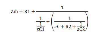
My problem arises when I try to determine the Q of this circuit. I solve for Z as seen from vin to vo (ie, R1 + the parallel combination of (1/(s C1) and the series combination of L1+R4+1/(s C2), in Laplace), and then solve for Q by taking the ratio of the reactance to the resistance at resonance. However, I get "0" , which makes sense, I guess, since I solved for the resonant frequency earlier by equating the imaginary part of the transfer function to 0.

Zin is :

Zin equation

I'm stumped -- How can I determine the Q of this network?

\$\endgroup\$
10
  • 1
    \$\begingroup\$ you need to derive the transfer function \$ H(s) \$ for this circuit. because there are 3 reactive elements, the transfer function will be 3rd-order. but Q is a parameter of a 2nd-order transfer function. if one pair of those poles is complex conjugate, then you have a 2nd-order portion with Q well defined. but if you have 3 real poles, then there are potentially 3 different Q (for each pair of poles) that you can define. \$\endgroup\$ Commented Dec 2, 2016 at 21:26
  • \$\begingroup\$ I have derived the transfer function --that is how I found omega at resonance. I then plug that resonant frequency, omega-0,into the impedance calculation of Zin --from that impedance, I thought I could get Q = reactance /resistance; ie, the imaginary part over the real part at the omega-0 I previously obtained. \$\endgroup\$
    – jrive
    Commented Dec 2, 2016 at 21:27
  • \$\begingroup\$ please edit your question showing the transfer function in terms of \$ R_1, R_2, C_1, C_2, L_1 \$. \$\endgroup\$ Commented Dec 2, 2016 at 21:29
  • 1
    \$\begingroup\$ given a general 2nd-order transfer function, you can express it in this form: $$ H(s) = \frac{b_0 + b_1 s + b_2 s^2}{1 + \frac1Q \frac{s}{\omega_0} + \left(\frac{s}{\omega_0}\right)^2} $$ from whatever multiplies \$s^2\$ in the denominator, you find \$\omega_0\$. and from what multiplies \$s\$, that (along with knowing \$\omega_0\$) tells you what \$Q\$ is. \$\endgroup\$ Commented Dec 2, 2016 at 21:32
  • 1
    \$\begingroup\$ I'd rather find resonance as maximum |F(jw)| and then the two -3dB frequencies and so Q=(fh-fl)/fo. Otherwise you may think of Q as 2pi times energy stored over dissipated one in one period. One more: sum all reactive powers over sum of active ones. Many different values are waiting for you. \$\endgroup\$
    – carloc
    Commented Dec 3, 2016 at 0:33

4 Answers 4

2
\$\begingroup\$

To calculate the Q, it is much easier to substitute numbers for the values of the components. Then use the Dominant Pole Approximation to find the Q. This works by separating the third order equation (which you have correctly solved) into a product of a first order system and a second order system. This separation process is hard if there are symbols for the polynomial coefficients.

The reason this is hard is that there are many different regions of the solution space, each with different circuit behavior and approximations for Q. Some of these symbolic solutions include terms that would be very small in a real-world circuit. These equation terms can be eliminated if the approximate magnitudes of the component values are known. Once enough of these simplifications have been made, the equations simplify, and the solution is typically dominated by the first order system or the second order system. If the solution is dominated by a second order system, Q can be found from that.

The more general definition of Q is that it is proportional to the ratio of energy stored in the resonator from one cycle to the next. This definition is useful for other resonators such as transmission lines. It also allows the use of time-domain calculations or simulations. There is controversy about the strict definition of Q.

\$\endgroup\$
1
\$\begingroup\$

To me, this question touches at first the DEFINITION of Q. The questioner (jrive) has just mentioned the letter "Q". What does this mean? For a bandpass, we can define the quality of the bandpass (selectivity) using the midfrequency-to-bandwidth ratio, however, her we have a third-order lowpass. In this case, how is the qualitiy factor Q defined?

I think - as mentioned already by Tom Anderson - we have no other choice than to use the quality factor of the complex pole pair of the circuit.

That means: We have to split the 3rd-order transfer function into a first-order expression and a second-order function (or, eqivalently, find the three roots of the equation) which allows us to define a Q-value (pole-Q=pole frequency divided by twice the real part of the pole pair).

\$\endgroup\$
0
\$\begingroup\$

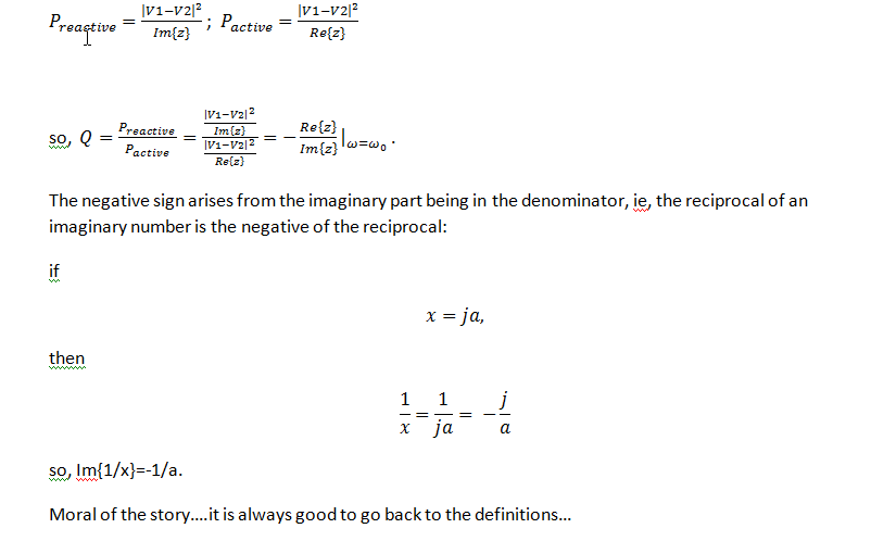
So, I was intrigued by how I was able to determine Q by taking negative ratio of resistance to reactance. I found the reason, and thought it would be good to share it with those of you interested.

I went back to the definition of Q: Q= Reactive Energy (or Power)/ Active Power (energy) evaluated at the natural frequency (undamped) (btw, resonant frequency approaches the natural frequency as the losses, R's, in the circuit approach 0. Using a simplified circuit example:

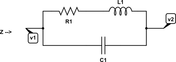
schematic

simulate this circuit – Schematic created using CircuitLab [ratio_reactive_to-resistive_power

\$\endgroup\$
0
\$\begingroup\$

The 100 Ohm Rin will badly load the node with L1 & C1.

If you can, modify the source to provide current, instead of voltage.

\$\endgroup\$
2
  • \$\begingroup\$ yes -- it was just a place holder for the calculation example. But, it brings me to something else that maybe you can help me with. I can solve the transfer function and see what is going on, but I don't have an intuitive feeling to how R1 loads the filter, or how the output at vo is multiplied by a gain of C1/C2 (assuming R4->0). Again, I can of course solve for all this with the transfer function , but I'd like to understand what is going on in a more intuitive way. Could you please provide some insight? \$\endgroup\$
    – jrive
    Commented Feb 28, 2017 at 3:58
  • \$\begingroup\$ --I've been trying to prove this to myself, and have not yet been successful. Assuming R4 is 0, the pi filter looks like an open at Resonance (correct?), so, you're left with a voltage divider between R1 and the impedance of the filtert at resonance. Since it is infinity at resonance, why does it matter what R1 is? \$\endgroup\$
    – jrive
    Commented Mar 2, 2017 at 19:07

Your Answer

By clicking “Post Your Answer”, you agree to our terms of service and acknowledge you have read our privacy policy.

Not the answer you're looking for? Browse other questions tagged or ask your own question.