2
\$\begingroup\$

In control theory, if the impulse response of a system dies out then the system is stable.

In electronics, Bode plot usually uses the see the gain and phase margins and determines the stability of a system.

Does the stability in the two fields mean the same? Also is there any relationship between them?

Update: In control theory, stability is defined as a measure of the tendency of a system's response to return to zero after being disturbed. So does the definition is also applied in electronics (for example OpAmp) and how to test it (say OpAmp) using this definition?

\$\endgroup\$
6
  • \$\begingroup\$ In electronics, a system may be considered only marginally stable if the step response has overshoot. I think this is why it is considered desirable to have sizeable margins. \$\endgroup\$
    – user57037
    Commented Dec 5, 2016 at 3:52
  • \$\begingroup\$ Stability and relative stability mean the same in all fields. The method of assessing it can vary. \$\endgroup\$
    – Chu
    Commented Dec 5, 2016 at 7:25
  • \$\begingroup\$ In control theory, stability is defined as a measure of the tendency of a system's response to return to zero after being disturbed. So does the definition is also applied in electronics (for example OpAmp) and how to test it (say OpAmp) using this definition? \$\endgroup\$
    – emnha
    Commented Dec 5, 2016 at 7:41
  • \$\begingroup\$ An op-amp IS a control system and subject to control theory therefore, your question becomes redundant because you are considering that an op-amp doesn't wholly fall under the mathematical umbrella of control theory. \$\endgroup\$
    – Andy aka
    Commented Dec 5, 2016 at 9:05
  • 1
    \$\begingroup\$ Both in electronics and in control theory, the poles of the final transfer function determine the stability of the system. If they are all on the left half-plane the system is stable. It is a property of the system and does not depend on the inputs. This may be applied to any system (hence, also those including OpAmps). \$\endgroup\$
    – Petrus
    Commented Dec 5, 2016 at 21:50

5 Answers 5

3
\$\begingroup\$

At first - two basic considerations:

  • The impulse response is a closed-loop test in the TIME domain (and can give you some rough "impression" regarding the degree of stability);

  • The BODE diagram is an analysis of the loop gain (loop open) in the FREQUENCY domain (and can give you some figures for phase and/or gain margin).

Hence, at first sight, both test are not related to each other. However, the term "stability" has the same meaning in both cases - and the mathematical tools of the system theory connect both domains to each other.

EDIT (UPDATE): Here is the desired answer to your update:

Regarding stabiliy there is, In principle, no difference between control systems and electronic (opamp based) applications. The DEFINITION of stability is in the TIME domain (BIBO: bounded input gives bounded output), however, the exact proof of stability properties (expressed in terms of stability margins) is conveniently done in the FREQUENCY domain (loop gain analysis). Note that this is one of the main reasons for introducing the frequency domain and the complex frequency variable s.

\$\endgroup\$
2
  • \$\begingroup\$ Thank you. Could you answer two questions on my update above and my question in Tony's comment? \$\endgroup\$
    – emnha
    Commented Dec 5, 2016 at 7:51
  • \$\begingroup\$ Yes - see the update section in my answer. \$\endgroup\$
    – LvW
    Commented Dec 5, 2016 at 10:18
2
\$\begingroup\$

They sort of meant the same thing.

An impulse has infinite bandwidth. The rise and fall time of an impulse are zero, that is what gives it infinite bandwidth. An impulse effectively applies all the frequencies to a system.

A bode plot sweeps a system through frequency. It does not get to infinity because it is not practical but the idea is the same. If the gain of the system falls below 1 before the phase reaches -180 degrees the system is stable.

\$\endgroup\$
3
  • \$\begingroup\$ Thanks, when using impulse to test for stability, assuming that the system is unstable, there is a frequency that causes oscillation. Now should we test one frequency component at a time to the system? The impulse input has infinite frequency components, so there is a frequency causing the system unstable. However, is the a possibility that other frequency components in the impulse will cancel the oscillation caused by one specific frequency component in the pulse? \$\endgroup\$
    – emnha
    Commented Dec 5, 2016 at 6:08
  • 2
    \$\begingroup\$ No, if the system is unstable and has the ability to oscillate at a certain frequency - it WILL oscillate at this frequency! The oscillation frequency will be INDEPENDENT on the test signal form (or frequency). \$\endgroup\$
    – LvW
    Commented Dec 5, 2016 at 7:50
  • \$\begingroup\$ Thanks. Can I understand it as below. The impulse has infinite frequency components. So we can apply the superposition to determine the response of the system. If the system is unstable, this means that there is a frequency fosc that causes the system to oscillate. The output will be sum of all frequency components response. For all frequency component except fosc, the response of it will die out. So the sum of all these components not including fosc will be died out also. Finally, the sum of all including fosc will oscillate. \$\endgroup\$
    – emnha
    Commented Dec 5, 2016 at 7:58
1
\$\begingroup\$

What you are referring to is more related to a root locus plot rather than phase/gain margin. It will show how the system will react to an impulse ( including oscillation ) and whether the system is underdamped or overdamped.

However this is different than gain and phase margin. The system could meet root locus stability criteria but have poor gain and phase margin. Gain/Phase show just how close a system is too having positive feed back.

For example: If the thermostat for my office was located far away and it took me to 10min. to walk there and back AND the temperature change also took >10min. I would be constantly walking back and forth trying to get the temperature right because I the temperature I would 'sense' would not necessarily be what I just set on the thermostat. If I were to add enough overshoot the temperate would go unstable. This poor phase margin.

\$\endgroup\$
4
  • \$\begingroup\$ Thank you. As my comment in the vini_i post, I would like to ask you this question too. When using impulse to test for stability, assuming that the system is unstable, there is a frequency that causes oscillation. Now should we test one frequency component at a time to the system? The impulse input has infinite frequency components, so there is a frequency causing the system unstable. However, is the a possibility that other frequency components in the impulse will cancel the oscillation caused by one specific frequency component in the pulse? \$\endgroup\$
    – emnha
    Commented Dec 5, 2016 at 6:09
  • 1
    \$\begingroup\$ ...."there is a frequency causing the system unstable". No - that is NOT correct. It is not the input signal that causes instability (oscillation). It is the internal positive feedback that causes SELF-EXCITEMENT - independent on externally applied signals. \$\endgroup\$
    – LvW
    Commented Dec 5, 2016 at 7:53
  • \$\begingroup\$ So instability is the internal property of the system not the external applied signal? For example, a system that has phase shift -360 degree and loop gain still larger than 0dB at frequency fosc. However, if the applied signal doesn't contain the frequency component fosc, then the system is still stable? \$\endgroup\$
    – emnha
    Commented Dec 5, 2016 at 8:04
  • \$\begingroup\$ No, the system will be unstable (and oscillating) - independent on the input signal. It is a matter of SELF-EXCITEMENT!. \$\endgroup\$
    – LvW
    Commented Dec 5, 2016 at 9:09
1
\$\begingroup\$

Stability means essentially the same thing in control, electrical, mechanical engineering.

Impulse response (or step response) is a rough and ready test to see 'how stable' a stable closed loop system is. It cannot be used on an unstable system. Many overshoots => marginally stable, 'dead-beat' response => very stable, 'one tiny overshoot' => perfectly OK (unless you cannot tolerate any overshoot (so OK on my baking oven, not OK on my epoxy curing oven)), 'crawls up to the final value' => too stable.

However, if a system is marginally stable, how do you improve it? If a system is unstable to begin with, how do you test it? If your system is big, expensive or dangerous, do you dare even switch it on closed loop? It's easy enough to switch on a small electronic circuit and see, but what if it's a 100MW rolling mill speed controller, or a mag-lev train rail guidance loop?

This is where open-loop Bode plot testing comes in. You measure the gain and phase of the open loop system as you sweep the excitation frequencies over a large enough range to capture all the useful behaviour of the system.

Once you have the Bode plot, there are various methods you can use to predict the stability of the system once the loop has been closed.

For a very simple low order system (unity gain stable op-amps are like this) you can simply look for gain margin and phase margin in the region of the unity gain response. Note that this sort of op-amp stability, where one time constant dominates, is designed to be simple, to the detriment of other parameters like speed. You can get faster opamps that are not unity gain stable, but you need to know what you're doing.

For higher order systems (almost anything with a motor in it for instance), this simple graphical approach is not enough, and then you can crank up more subtle and mathematical methods like root locus plots and the Routh-Horowicz criterion, both made my head ache in my student days.

When a system is unstable, it will always tend to oscillate, even when the input is held at zero. The reason is there is noise always present in any real physical system, it's part of the physics and cannot be reduced below a certain magnitude. This noise contains energy at all frequencies, and will be amplified by the system and eventually grow until the system is crashing against the end-stops.

\$\endgroup\$
1
\$\begingroup\$

Caution: you cannot trust OpAmps at high frequencies. They cannot control their Vout, and you'll get surprised.

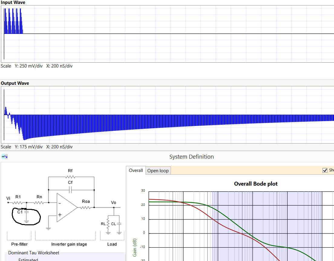
An Impulse is a useful input signal, because active LowPassFilters will let some of that Impulse appear on OpAmp's output. WaltJung warned of this. We honor WaltJung in the canned-example tool called Signal Wave Explorer; simply click the topleft "examples" button, select "Beware the Active Filter", then drop to bottomleft and click "Run". You'll learn that enabling/disabling C1 is the key to successful "filtering" of an impulse. enter image description here Where do impulses occur? Consider an LCD display, where 10 nanosecond RowDrivers couple into the magnetic loops of a touch-screen pen tracker. Installing C1 was the key to success for that project.

You can download Signal Wave Explorer, for free, from robustcircuitdesign.com

\$\endgroup\$

Your Answer

By clicking “Post Your Answer”, you agree to our terms of service and acknowledge you have read our privacy policy.

Not the answer you're looking for? Browse other questions tagged or ask your own question.