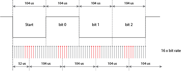
The data is received on the RXx/DTx pin and drives the data recovery block. The data recovery block is actually a high-speed shifter operating at 16 times the baud rate, whereas the serial Receive Shift Register (RSR) operates at the bit rate.
-
\$\begingroup\$ So that it can get enough samples to recover the transmit clock. \$\endgroup\$– Ignacio Vazquez-AbramsCommented Dec 5, 2016 at 7:01
-
1\$\begingroup\$ If you know that I intend to hit you with a brick would you be alert/observant? \$\endgroup\$– seetharamanCommented Dec 5, 2016 at 7:24
-
\$\begingroup\$ The data clock is synchronized to 8 of 16 clock cycles after leading edge of the start bit for asynchronous operation. \$\endgroup\$– D.A.S.Commented Dec 5, 2016 at 7:27
2 Answers
The receive clock is not synchronized to the transmit clock, nor are the clocks necessarily exactly correct to their nominal frequency (and they could be 'off' in opposite directions).
It could work with fewer samples if the clocks were exact and the data noise-free, but more is better (with diminishing returns) and allows more tolerance of clock errors etc, so 16 is a good number.
Here (for the 6402 UART) you can see that the area A represents the uncertainty in the location of the incoming start bit edge, as much as +/- 1/32 of the receive clock. The center of the start bit is assumed to be 7.5 clock cycles after the start bit is detected. Subsequent incoming bits are timed from this.
Why Data Recovery Block needs to operates at 16 times the baud rate
It doesn't but 16x the baud rate is usually deemed a good number to use. Look at the diagram below: -
Upon receiving the falling edge of the start bit, a 16x clock is started and, after 8 counts the middle of the start bit is located. A "full" count of 16 is then initiated. This count terminates right in the middle of the 1st bit (bit 0). At this point the the first bit of the byte is stored. Thereafter, each subsequent bit is sampled in the middle of each bit until the full byte is stored.
However, if the incoming baud rate changed a little bit (up or down) the system would still cope but, progressively, in the absence of bit changes, the sampling of the bit would get pushed closer to the leading or trailing edge of the bit. This isn't too bad of course but, with fewer sample counts, the granularity of the counting might mean that at the extreme limits of the incoming baud rate, an error will occur. So, 16 is chosen as a matter of convenience and performance but certainly, an initial count of 4 followed by counts of 8 could be implemented.
In reality, the 16x clock is running all the time and so there is also a granularity effect when determining the exact time of the falling start bit. This is another small error that is much helped by running at a higher clock speed.
See this answer also.


