In asynchronous data communication, Initiation of data communication between two stations(sender and receiver) involves synchronizing their clocks to ensure both stations are agreed upon same bit times. How does this process takes place? How do sender and receiver agrees on same clock period? If possible point me to some resources too.
4 Answers
This clock sync doesn't necessarily happen before; it often happens before, and during transmission.
The things you might want to read in the usual literature (especially: Sklar and Proakis, imho) is timing synchronization.
How to implement that depends on a lot of unknowns, so I can't give you one answer. In reality, there's literally hundreds of approaches to synchronize timing, and which one you choose depends, among a lot of other things, on
- physical relation of symbol rate and carrier frequency
- modulation
- signal model
- statistical noise model
- statistical interference model
- receiver imperfection models (nonlinearities, I/Q imbalances, clock drifts, sampling jitter, …)
- length of transmission
- coherency time of your channel (which is closely linked to)
- doppler bandwidth of your channel
- statistical model of the clock offsets
- affordable overhead for CSI acquisition vs. payload data rate
- receiver operation characteristics, ARQ vs robustness trade-off etc
- memory available at receiver
- computing power available at receiver
- power consumption limits and tradeoffs
- MIMO necessity
- receiver cost vs BER tradeoff
- Channel coding used (effect of SER, in the end)
- multi-user capabilities
If you pick any of these books, they'll probably introduce some classical synchronizer – and you can still find those in application very often! But all of these are already relatively application-specific. For example, a control loop that stabilizes a QPSK reception doesn't necessarily (and usually: won't, because a few mathematical tricks don't work here) work for 8PSK.
If you're really just interested in timing estimation happening before actual payload transmission, you're after preambles. Those are known sequences that the receiver looks for to estimate the parameters of the channel and transmission – timing is one of these parameters.
Transmission begins by encoding the discrete-time symbol stream \$s[n]\$ to a continuous-time baseband signal \$y(t) = b(s[\lfloor\frac{t}{T_0}\rfloor])\$.
In a simple baseband system, this is transmitted as-is:
\$tx(t) = y(t)\$
On the receiving side, the signal has run through an LTI system with a basically unknown impulse response \$h(t)\$ that includes a gain factor, there is additive noise, and the symbol period \$T_0\$ has an additional error term as well:
\$rx(t) = y(t)\ast h(t)+N(t) = b(s[\lfloor\frac{t}{T_0+T_e}\rfloor])\ast h(t)+N(t)\$
We know that
- \$h(t)\$ is causal, and close to \$\delta(t)\$, and
- \$T_e\$ is close to 0,
so not all hope is lost. For slow transmissions, it is often possible to ignore these terms completely, or see them go away after sampling.
For example, a UART connection that samples the first data bit one and a half bit times after detecting the first edge of the start bit (\$t_0\$):
\$s[1] = b^{-1}(rx(t)\ast \delta(t-\frac{3}{2}(T_0+T_e)-t_0)+N(t))\$
Now, if \$|h(t)|<\epsilon\$ for \$t>\frac{T_0}{2}\$, we can be fairly certain that the value at the sampling point is affected only by the sender's signal, the channel's gain factor, and the noise picked up in between.
For RS-232, we can use
- \$b(MARK) = -12V\$
- \$b(SPACE) = 12V\$
and the inverse
- \$b^{-1}(x) = \left\{\begin{array}{l}MARK, & \textrm{if }-3V > x > -15V,\\ SPACE, & \textrm{if }3V < x < 15V,\\ ERROR & \textrm{otherwise}\end{array}\right.\$
If \$|N(t)|<3V\$, we can then ignore the noise term. Since we allow lower voltages on the receiver side, we can also deal with any gain between \$0.5\$ and \$1\$ easily. If the gain happens to be \$0.75\$, then we can even deal with noise up to \$\pm 6V\$, so there is usually a relationship between error terms as well.
This leaves the \$T_e\$ term. The sampling points are spaced out evenly at \$t_n=t_0+\frac{1+2n}{2}(T_0+T_e)\$, so the sampling point in the bit period shifts by \$T_e\$ in each bit. For larger \$n\$, we either get to the point where \$h(\frac{T_0}{2}+nT_e)>\epsilon\$ (i.e. the sampling point is still affected by the previous symbol, with \$T_e<0\$), or \$h(\frac{T_0}{2}-nT_e)>\epsilon\$ (i.e. the sampling point has slid into the next symbol, with \$T_e>0\$).
RS-232 solves this by limiting \$n<11\$, and resynchronizing afterwards.
For other protocols, it always boils down to identifying the error terms and either finding conditions under which errors can be ignored, or actively correcting them.
For example, if you can determine a time-discrete \$h[N]\$ transfer function for your transmission channel (where N is oversampled n), then you can apply \$h^{-1}[N]\$ numerically -- for this to work, you need a startup phase for your connection that allows you to determine \$h[N]\$, such as the training phase in analog and DSL modem connections).
If you have modulation and demodulation steps in between, that results in error terms for the clock difference of the modulation and demodulation clocks -- determine and correct these if needed. If you use a direct quadrature modulator or demodulator, you get error terms for gain difference, phase offset (difference from 90 degrees) between I and Q channels and DC offset per channel. For a superheterodyne system, there are fewer error terms, but \$h(t)\$ will be more difficult to compensate for.
To compensate for clock drift, you can build a circuit that attempts to recover the sender's clock from the data stream. This works significantly better if the data is encoded in a way that guarantees an edge to synchronize to after a limited number of symbol times -- for example, 8b10b encoding on PCIe links.
All of these rely on a protocol convention between sender and receiver that allows the receiver to determine the absolute value of an error term. Depending on the application, these measurements are performed once at setup, continually, or at certain time intervals:
- UART determines start time with a start bit and ignores error terms because they are too small to affect transmission
- PCIe does a short link training phase and continually adjusts later on
- DSL does a long link training phase and continually adjusts later on. The training phase is that long because the transfer function \$h(t)\$ is still likely to have large values for \$h(nT_0)\$ with \$n=1,2,3\$.
- WiFi does a short link training phase with a preamble before each packet
- USB up to 2.0 has a fairly short preamble, and I think they do at least some synchronisation inside the packet as well
- most QAM based modulations have a pilot symbol at defined intervals that has known amplitude and phase in the baseband
- QAM+OFDM modulations can use a continuous pilot in a subchannel, or pilot symbols at defined intervals in each subchannel (the latter compensates for the frequency response of the band used)
- ...
-
\$\begingroup\$ wow... +1 for the answer, although I'm not sure I would call your answer understandable. I've been working on various communications systems (everything from your basics to high speed PCIe and USB3) for close to two decades now and your answer just reminds me of why I dropped out of school. :-/ All the information is there but it's unapproachable. \$\endgroup\$ Commented Nov 12, 2016 at 14:33
-
\$\begingroup\$ My experience is that different people need different approaches to problems, so I wanted to give a complementary answer to the ones already present. \$\endgroup\$ Commented Nov 12, 2016 at 15:04
-
\$\begingroup\$ I completely agree, which is why I +1'd your answer. \$\endgroup\$ Commented Nov 12, 2016 at 15:05
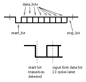
For a simple UART, the data speeds must be agreed upon beforehand but, to synchronize the receive clock with the data requires a clock that runs several times faster than the data rate. Synchronization takes place as follows: -
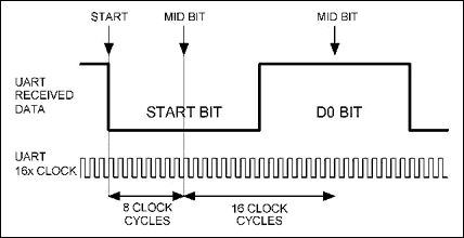
The "fast" clock in this example runs 8x faster than the bit rate and every positive edge of the clock it tests the data looking for a start bit. When that happens, the circuit waits 12 fast clock cycles and "measures" the value of the first bit. From that point, it would measure the data every 8th clock cycle. Here's a bit more detail with a UART that uses a 16x clock: -
I've not gone into some subtleties such as multiple symbol testing to ensure there isn't noise present.
Some good answers already, it would be good if you could indicate if you were more interested in the selection of bit rate or the maintenance of clock drift or error.
The fact that you mention asynchronous communications could mean that you are interested in how the bit sampling intervals are established and two of the answers cover that mid bit sampling determination very well. This feature is handled by a UART IC or software library if implementing a bit-banged serial interface. The only time you need to get involved is curiosity or if you plan to write your own bit-banging code.
Clock drift over a single ASYNCH word can be 5% total for TX and RX if all other things are equal but way more than any crystal or resonator would be able to drift. Resistor and silicon-based clocks with or without trim can also usually achieve 5% combined error. If both ends suffer loose timing then the max error is 2.5% each to accommodate the two errors in opposition (one slow, the other fast)
However you could also be interested in how the bit rate is selected (reciprocal of the bit period) at the start of communication. This is a higher level activity that is generally not done with hardware and usually avoided if possible by making the user select a common bit rate on both sending and receiving device. If this deterministic operation is impractical or impossible then one or the other device has to use intelligence to make the determination. If you have a simplex (one direction) data link the receiver has to do the determination, if you have a duplex link the same is possible and there is an option for the sender to take part in the process. The classic example of where this bit rate determination was used is in legacy RS-232 smart POTS dialup modems. The most popular auto-baud system was facilitated by the Hayes Corporation AT command set. They also held the patent for the idle +++ idle in-band command mode request that was hijacked/adopted by the industry at large. They required the sender to send a specific character string as the first two characters when initiating communications. The string was the (upper case) AT character sequence that they used for most of their command prefixes. The first time it was sent the modem would be in a waiting state that would use some measure of non-standard receiver logic (I am guessing that it was set to the max bit rate and it had a lookup table that used the gibberish to determine the parameters for slower bitrates) to parse the expected bit sequence. From this it could determine the UART parameters of the sender specifically word length, parity status and bit rate. It would then set the internal parameters to match and further communications would be reliable from the next character onward. Another method was for the sender to send a reset command and wait for a readable ACKnowledge reply. If the bit rates did not match the receiver would either not reply if it had not decoded any characters or possibly send a NACK if it was not decoded as a known command. The sender would keep trying all the available parameters hoping the receiver was set up to receive using one of them, at this point the ACK would indicate a match and the rest of the communications would be matched for bit rate.


