4
\$\begingroup\$

What are exactly the pros/cons of changing the PWM frequency?

I don't think I need to change any PWM frequency at this very moment - but since I don't know the benefits of doing it, how can I really know if it's useful for me?

I'd like a general answer (which I and other people reading this post can apply in different situations), but if someone wants some data to answer, here are those of the project I'm working on at the moment:

  • ATmega328 microcnotroller @16Mhz (it stands alone, it's not in an Arduino board)
  • 4 independent small brushed motors, each with a propeller (propeller's diameter: around 6 cm), on pins 3,5,6,11, controlled by a BUK9840-55 trasnsistor (datasheet)
  • a simple RF receiver is placed nearby and needs to receive a 433MHz signal (the RF comminication is quite slow (500bits/sec), and doesn't need to be very reliable).

EDIT: how does the PWM speed influence the RF communication?

\$\endgroup\$
2
  • \$\begingroup\$ The obvious question is what PWM frequency are you using by default? If we can use your project as an example we can put the answer in a useful context. \$\endgroup\$
    – user98663
    Commented Dec 11, 2016 at 13:07
  • \$\begingroup\$ I'm using a 490Hz PWM \$\endgroup\$ Commented Dec 11, 2016 at 20:24

6 Answers 6

3
\$\begingroup\$

PWM units, typically, work the following way, or equivalent¹.

Set up:

  1. an initial output value, ie. either high or low and
  2. the "counter reset value", to which the counter is reset after reaching
  3. the "counter maximum value", as well as
  4. the "counter flip value", where the output state is toggled

After that, you just let the counter run – for example, you might set

  • initial state high,
  • reset value 0,
  • max value 100,
  • flip threshold 25

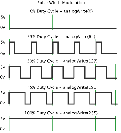
Then your counter would start at 0, and increment once every clock cycle, and at 25, the output would be set to low, until the counter reaches 100 and is reset to 0. That way, the output would be high for 25 time units, and low for 75 – a duty cycle of \$\frac14=25\%\$.

Now, the PWM frequency is typically defined as the time between the reset and reaching the maximum.

So, this inherently is one aspect of choosing a PWM frequency: if there's 100 time units (which, by the way, are typically clock ticks of something like the CPU clock divided by some \$N\$), your duty cycle "granularity" cannot be better than 1%.

On the other hand, if you let's say set the max value to 106, then you might get super nice resolution on the duty cycle, but that doesn't help you, because now the output might be low and high for so long that whatever you drive with the PWM simply sees "on" and "off", unless you go through great lengths (build a mechanically large low-pass filter) to "smoothen" things out, and then you'd lose all ability to quickly adjust the duty cycle (because the filter will also smoothen out your adjusting).

PWMs are used for very different things – for example, to generate an analog voltage, as mentioned above, by low-pass filtering. In that case, using a high frequency might be beneficial, because your low-pass filter, needing to cut off the PWM frequency, is much easier to build when that frequency is high. On the other hand, in circuits where you work with sensitive analog voltages, having a fastly switching PWM signal is dangerous, due to that signal potentially coupling over.

Other uses are, and that's probably what your motor does internally, more digital: the PWM simply controls for how long something is switched on or off, for example, the internal power supply in DC brushless motors (which are, in fact, 3-phase AC motors that have a supply that generates three sine signals from the DC voltage it takes). For these applications, as said, the PWM frequency mustn't be too low, because then your motor will stop, start, stop,…, but it mustn't be higher than the frequencies the internal supply uses to generate the AC voltages.

Yet other uses are actually signal generation usages – for example, assume you have a microcontroller with a CPU clock of 16 MHz, and you want to generate a set of different frequencies (for example, you have a Modem that uses frequency shifting as modulation, so one frequency means "0", the other one means "1") – in that application, you might use a fixed duty cycle, and what you're really interested in is the PWM frequency!

There's also devices that communicate measurement values by PWM duty cycle – or take PWM duty cycle as input, for example these "neopixels" that you might have heard of. Of course, their interface controller has a specific timing range, so you have to configure your PWM frequency to make things work.


¹ this, for example, assumes you can both set the upper and lower limit, and that the counter counts up – there's no reason that all of that is true, you can implement PWM by counting down, or by not having a variable upper limit, but that's details.

\$\endgroup\$
2
\$\begingroup\$

The Arduino PWM mode runs at 490 (or 980) Hz depending on the board, and is intended for simple applications like LED dimming and DAC (digital-to-analog conversion), and playing with cheap (high resistance/inductance) motors. Keeping the frequency low and fixed makes these sorts of circuits consistent across all Arduino boards which reduces the learning curve, which is sort of the idea for the platform.

Consider the DAC example. If you allow the user to easily mess with the frequency, they would need to recalculate the R and C values to effectively filter the new PWM frequency.

The LED dimming example could benefit from being able to run the PWM slower, but you can get the same effect by bit-banging and using the delay function (run it 5s on, 5s off; then 500ms on, 500ms off; then 50ms on, 50ms off).

When you want to do 'useful' stuff with PWM, you need to have frequency control. Motor control, for instance. The optimal PWM frequency is going to depend on the motor itself (inductance and resistance) and often is best to test empirically vs. looking up a value from a datasheet. The losses in the driver will also play a role.

Switching power supplies are another example. The switching frequency of a PWM-driven converter will impact both the peak current and the switching losses in the driving elements.

For your specific example, I would consider bypassing the usual Arduino PWM stuff and talk to the hardware, and experiment with which frequency makes your motors and driver FET happy. Keep an eye on the safe operating area of the FET and make sure it doesn't get too hot.

\$\endgroup\$
2
\$\begingroup\$

You added the question:

EDIT: how does the PWM speed influence the RF communication?

Well, let's assume we're just dealing with 50% duty cycle PWM – square waves. It's easy to show this applies to other duty cycles with small modifications to the result.

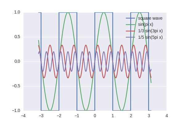
A square wave is composed of sines:

sines

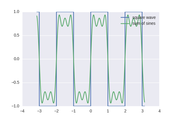
and if you add up these weighted sines, you approach the square wave:

sum of sine

Exactly speaking, $$ f_\text{square}(x) = \sum\limits_{n=0}^{\infty} \frac1{2n+1} \sin\left(2\pi (2n+1) x\right) $$

So, a perfect square wave contains harmonics at the square wave frequency, and every odd multiple of it – so if you want to communicate at 30 MHz, it would be a very bad idea to have a PWM with a 10 MHz frequency.

\$\endgroup\$
1
\$\begingroup\$

Consider running a very small DC motor using a PWM frequency of 1Hz. You won't be able to speed control it very well at all because it's just going to sit there twitching. A small motor can easily spin up and down again in 1 second.

This is a because of the motor's low rotational inertia - your 1Hz PWM is no better than simply pressing and releasing a button with your finger.

Consider the same system using 1000Hz instead. You can fit many PWM pulses into the time it takes for the motor to spin up or down. At this point, the motor effectively becomes a low pass filter and finds equilibrium spinning at a rate that is proportional to (PWM ratio) * (supply voltage).

For motors in particular, it is a good idea to pick a frequency that allows smooth speed control, but not so high that the windings in the motor will begin to act against you and you lose efficiency to back EMF and inductive effects.

That's a general answer pertinent to motors (as you mentioned using them). Other applications (resistive or capacitive loads) will have different reasons for choosing sensible frequencies.

\$\endgroup\$
0
\$\begingroup\$

PWM is a abbreviation of Pulse Width Modulation.

PWM Description by arduino.cc

Changing the PWM frequency increases the precision of pin voltage.
Increasing PWM frequency decreases the time per cycle.

Pros

  • Increased precision.

Cons

  • There are limitations of increasing PWM frequency; you cannot increase over the chip frequency.
  • Using the external Library uses memory.
\$\endgroup\$
3
  • \$\begingroup\$ The OP said it's not an Arduino project. IIRC those functions you mentioned are from Arduino libraries. \$\endgroup\$
    – user98663
    Commented Dec 11, 2016 at 13:34
  • \$\begingroup\$ Oh... I see. Should I remove the answer? Because @Wossname you are right. (It is my first answer and I think I made a very big mistake) \$\endgroup\$
    – maxswjeon
    Commented Dec 11, 2016 at 13:39
  • \$\begingroup\$ don't worry about it, the OP wanted "general" answers anyway, but you might consider using "cons" that aren't arduino specific :) \$\endgroup\$
    – user98663
    Commented Dec 11, 2016 at 13:42
0
\$\begingroup\$

The industry has shown that "harmonics do not exist", because the basis functions for FFT are sins and cosines at 1...N multiples and the FFT can only model signals as sums of what its allowed to use. Thus the 433,000 harmonic of 1KHz does not tell use much about impact on RF link success, because.....see next paragraph.....

....more importantly, you must avoid BLOCKING (overloading) the 433MHz front end with trash; if you totally upset the RF frontend operating point during your PWM/motor transients, your receiver will hiccup, unless your bit-durations are LONG. Your 500Hz bittimes may indeed be able to overcome motor spikes.

For the receiver to succeed, use a HIGH PASS FILTER PI network between antenna and FrontEnd. Place your HighPass corner approximately 200MHz, so you get little penalty at 433, but the 1,000Hz and the 1uS spikes get seriously attenuated. Try a 2-pole or 3-pole or 4-pole HPF if needed.Also, shield the receiver; use Cap-FerriteBead-Cap-Fb-Cap filtering for its power. Also place 10KOhm resistors in the handshake/databuss to/from the receiver.

\$\endgroup\$

Your Answer

By clicking “Post Your Answer”, you agree to our terms of service and acknowledge you have read our privacy policy.

Not the answer you're looking for? Browse other questions tagged or ask your own question.