2
\$\begingroup\$

On a 25W max power (10V p2p @ 4ohms) balanced (push-pull) high level output factory car audio head unit from which I need to feed a mono amplifier (for subwoofer) that only has an unbalanced line level input (0.15V-3V @ 10kohms), should I make my voltage divider to match the amps' input impedance or simply give it a 1kohms output impedance to make it a little more "universal"?

I want to bring the signal down to 2V p2p so I could either use 20k/10k or 3.6k/1k (or even lower) then go through a 10uF DC filtering cap. Which would be better practice?

\$\endgroup\$
2
  • \$\begingroup\$ I initially thought I could use the HU's positive speaker wire only in ref to GND but I realized that I would only get 180° of the signal! \$\endgroup\$
    – Ghyslain
    Commented Mar 7, 2012 at 3:52
  • \$\begingroup\$ 10Vpp in 4 ohm is not 25W. More like 3W. \$\endgroup\$
    – radagast
    Commented Aug 21, 2013 at 11:27

3 Answers 3

1
\$\begingroup\$

It depends on the type of output your "head unit" has what solution you can use here.
Are you sure it's not just a single ended push-pull output? What does the manual say exactly?

Assuming it's a truly balanced output (i.e impedance matched) then it may be transformer coupled, or actively balanced using two driver ICs or single ended with impedance matching from pin 3 ("cold") to ground. If it's just a "quasi" or "pseudo" balanced (made by just adding an inverted output but not impedance matched) then you must be a bit careful and not connect the cold side to ground.

The connections for the transformer balanced situation would be hot wire (XLR pin 2) to the unbalanced input, and cold (XLR pin 3) to unbalanced ground (you can connect pin 1 to pin 3 for cable shield)
This method can also be used in the case of a truly balanced impedance matched active output (shown in bottom picture as "Typical Pro Output"), but do not connect the equipment grounds together (don't connect shield at both ends)
Here is an example of a transformer balanced output to unbalanced input connection:
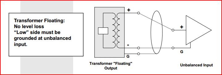
Balanced to Unbalanced Transformer Output

For a standard push-pull output, connect pin 2 to unbalanced input, pin 1 to input ground and leave pin 3 floating, do not attach it to ground (with a standard push-pull output it may cause overheating of the drive IC)
You will still get the same signal, it will just be half the amplitude of the balanced signal, which is fine since you want to cut the level in any case:

Balanced to Unbalanced Push-Pull Output

The best method for interfacing a balanced/push-pull active output to unbalanced input is to use a transformer, preferably with the winding ratio to attenuate as desired:

Balanced to Unbalanced with Transformer

The above methods can be used with a suitable divider for level matching. Make the divider output impedance around 1/10th or lower of the input impedance so as not to load the divider too much.

You will get widely ranging views on the best way to interconnect balanced and unbalanced equipment (especially about how to connect the shield wire), so in order to avoid confusion try and understand what is happening, why certain approaches might not be a good idea and what to try if you get problems.
When testing at first, check with a scope/multimeter to make sure you have not shorted anything to ground that shouldn't be (check current flow and voltage levels - you can also use an appropriate fuse to protect outputs if they don't already have one present)

Here are a couple of decent links to get you started:

Interconnection of Balanced and Unbalanced Equipment
Balanced and Unbalanced - How to do it right
ESP Audio Pages (same site linked to in Danny Kmack's answer - from what I've seen of it it's an excellent source of reliable information)

\$\endgroup\$
0
\$\begingroup\$

This amplifier is driving speakers at the same time, and the idea is to just tap into the signal for a sub, right?

One idea is to just use the speaker as part of the voltage divider. Put a small resistor (say 0.5 ohms) in series with the speaker load. This will develop a small voltage proportional to the speaker current, with a small source impedance: two birds, one stone. Won't give you 2 volts though: but isn't there some gain in that line input.

The speaker current signal is not exactly the amplifier's output voltage signal. It is the signal modified by the speaker impedance. Using that as the basis for the subwoofer signal should be fine since it gets severely low-pass-filtered anyway.

A current-sensing resistor like that in such an arrangement used for implementing negative current feedback, found primarily in guitar amps nowadays.

\$\endgroup\$
0
\$\begingroup\$

The best way to do this would be to unbalance the line by using a differential amplifier (an op amp will work) and then bring the voltage down using either another op amp or a voltage divider.

Depending on the type of amplifier you have, I would not worry about impedance matching. Transistor amps typically have such high input impedance that only an extremely low output impedance from the previous stage could cause a problem.

If the positive speaker wire referenced to ground is 180 degrees out of phase, the negative speaker wire will be in phase when referenced to ground. However, I was under the impression that the positive wire was the in phase wire in a balanced line.

If you would like to learn more about balanced lines and converting them to an unbalanced line, I highly suggest this link: https://sound-au.com/articles/balanced-2.htm

\$\endgroup\$

Your Answer

By clicking “Post Your Answer”, you agree to our terms of service and acknowledge you have read our privacy policy.

Not the answer you're looking for? Browse other questions tagged or ask your own question.