1
\$\begingroup\$

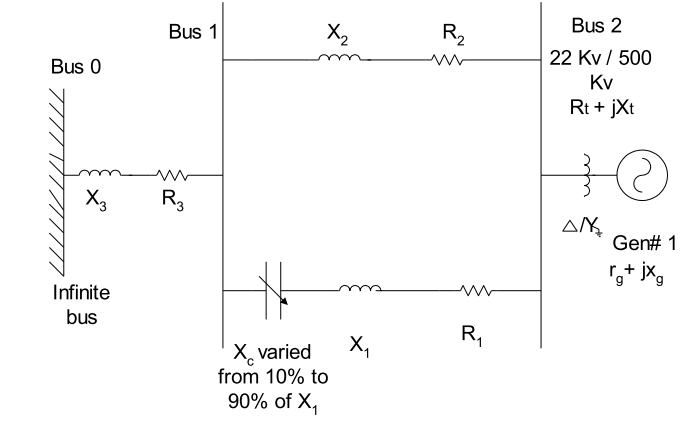
So this segment of transmission like has inductance, resistance and a capacitor in series in one of the branches. Circuit They have calculated the equivalent impedance as follows:
Assumption 1

Assumption 2

Impedance expression

My question is, in the calculation of the total impedance why is the angle of the inductive reactance taken to be negative and that of the capacitive reactance taken to be positive? I thought it was supposed to be the other way around? like below: enter image description here

\$\endgroup\$
2
  • \$\begingroup\$ Where? I see Inductor <90' Capacitor <-90' \$\endgroup\$
    – D.A.S.
    Commented Jan 4, 2017 at 8:16
  • \$\begingroup\$ This model is flawed for the Transmission Line and does not show the shunt admittance \$G+j\omega C\$ Reference link? We know that a transmission line \$Zt=\sqrt{\frac{R_t+j\omega L}{G_t+j\omega C}}\$ \$\endgroup\$
    – D.A.S.
    Commented Jan 4, 2017 at 14:24

1 Answer 1

2
\$\begingroup\$

enter image description here

It looks like a mistake to me because they use the +X\$_G\$ inductive reactance value near the start of the equation and thereafter, the inductive reactances are treated as negative values. It has to be a mistake or some cunning plan that the context of your question doesn't cover.

\$\endgroup\$
1
  • \$\begingroup\$ I didn't spot that. Thanks Andy. Should be a mistake then. The purpose of this was to simply find the impedance between the infinite bus and the generator (including the generator impedance), no cunning should be involved hehe. \$\endgroup\$
    – CKCK
    Commented Jan 4, 2017 at 20:31

Your Answer

By clicking “Post Your Answer”, you agree to our terms of service and acknowledge you have read our privacy policy.

Not the answer you're looking for? Browse other questions tagged or ask your own question.