The behaviour of an inductor takes most people by surprise initially.
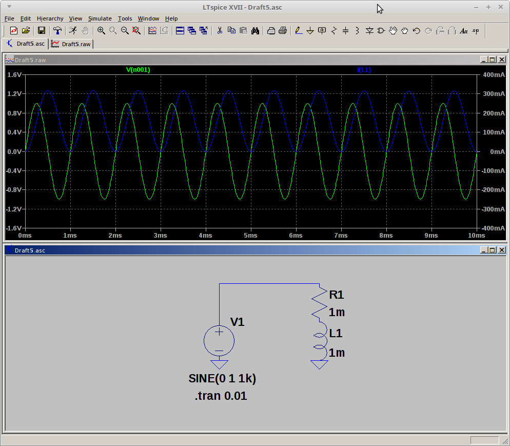
In answer to comments here, and your other question, let's see what the current in an inductor does when fed with a sinewave voltage source, everything starting at 0. This is produced in LTSpice XVII, running under Wine 1.8, under Linux Mint 18

The inductor current (blue, right scale) starts from 0, builds, falls again to 0, builds again. It stays positive valued only, at least over this time scale with these conditions, in an offset cosine fashion. The conditions are, the inductor series resistance is very small, only 1mohm. As the inductor inductance is 1mH, that gives a time constant of 1 second, L/R. As we are looking out only to 10mS, very little changes in that time.
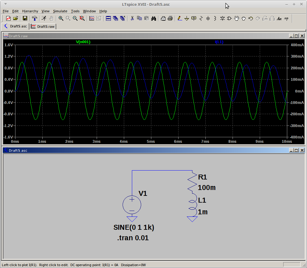
Now let's have a look with a larger value of series resistance. I change the R to 100mohm. This gives an L/R time constant of 10mS.

What's happened? Now we can see the transient behaviour starting to die out, the blue current trace is moving down to become centred around 0. After one time constant, it's got a bit more than halfway to where it's going.
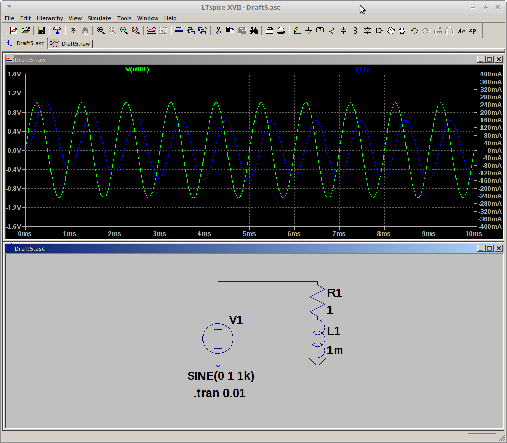
Let's try looking out even further, and use an L/R of 1mS.

Now by the end of the 10mS trace, 10 time constants, the current trace has completely settled down to being bipolar around 0. In fact, if you look back, it's not visually distinguishable from that after 5 time constants
If R was zero, then the initial transient would continue indefinitely, as the L/R time constant is infinite. That's where the continuous current in superconductors comes from, it's a transient that doesn't die away.
Compared with Capacitors
If you want to understand inductors by comparison with capacitors, then it can be done, but you need to take the dual circuit. That means switching series for shunt, and current for voltage.
Consider a sinewave current source starting at 0, feeding a capacitor with initial zero voltage. The voltage will build from 0, peak, fall back to 0 again in an offset cosine fashion. You can use the traces above to illustrate what happens, green trace as the current source, and blue trace as the voltage. For the simple capacitor case, the traces are as in the first, transient only, plot.
Now if you add a shunt resistor across the capacitor, the offset voltage will fall, bleed off through the resistor, and eventually its voltage will be swinging equally about zero, as in the third plot.


