4
\$\begingroup\$

I have a H-Bridge based Inverter that modulates a 350VDC source into 220V RMS @ 50 Hz. Right now I'm working at just 70VDC but my output inductor is getting quite warm. Here is a schematic:
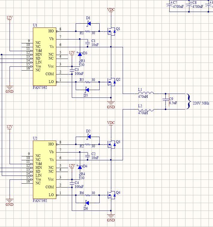
enter image description here

The output inductors, L1 and L2, both get quite warm when the DC source is at 70VDC. I haven't gathered the courage to go higher voltages. The switching frequency for my PWM is 16KHz. I have no load on the inverter. By adding a 1.95 Ohms shunt resistor I was able to measure the RMS (I assume mostly reactive) current, which was approximately 400mA. Note that the output waveform looks extremely good and relatively free of ripple, even under some load.

The particular inductor I'm using is 2320-V-RC. The DC Current rating is 3.8A. I don't have enough experience with filters meant for power to know if I should be using a different type of filter or a different sized inductor.

\$\endgroup\$
1
  • \$\begingroup\$ Your system is a switcher. Thus the mean current through the inductor may be below its DC current rating but the peak current might be above the peak current rating of that inductors. You should check what the expected peak current is, and verify that your inductors can handle it. \$\endgroup\$
    – Blup1980
    Commented May 21, 2014 at 10:41

2 Answers 2

5
\$\begingroup\$

Almost certainly your inductor core is saturating. The currents into the 6.5 uF will be quite high and this is the reason. You have basically a series tuned circuit formed by 2x 470uH and a 6.5uF capacitor.

This will have a resonant frequency of: -

f = \$\dfrac{1}{2\pi\sqrt{LC}} = \dfrac{1}{2\pi\sqrt{0.001\times 6.5\times 10^{-6}}}\$ =1974 Hz.

Ideally, you want the resonant frequency to be logarithmically half way between 50 Hz and 16 kHz and this would be more like 894 Hz so maybe you are a little close to the switching frequency. You could probably go lower - maybe towards 300Hz to improve this but, all the time the inductor or the cap is getting bigger.

Basically if you could raise your PWM frequency by 3 or 4 times you'd see an improvement I reckon.

\$\endgroup\$
2
  • \$\begingroup\$ I see, but bigger capacitors rated for 220V are too expensive. Is there no alternative? \$\endgroup\$
    – Saad
    Commented May 21, 2014 at 11:29
  • 1
    \$\begingroup\$ Bigger inductors and / or higher switching frequencies are my recommendation. \$\endgroup\$
    – Andy aka
    Commented May 21, 2014 at 11:42
3
\$\begingroup\$

First of all, note that that family of inductors has their current rating set by a 30°C temperature rise, and that they also lose nearly half their inductance at that current. I think that for this application, you're going to want much beefier inductors to start with.

As far as the filter design itself, you basically want the inductors to block as much 16 kHz energy as possible, while having a minimal impact at 50 Hz. For example, if you made them 1500 µH each, they would add less than 1 Ω of total reactance at 50 Hz, but would have an impedance of about 300 Ω at 16 kHz, passing only about 733 mA(RMS) at the full voltage. I just pulled the 1 Ω number out of the air; the key point is that you want this value to be less than the effective source resistance of the H bridge, but about the same order of magnitude.

But the key point is, the inductors need to maintain this level of inductance even while they're carrying the peak value of the 50 Hz load current plus the peak switching current, and it is going to require a physically large inductor to accomplish this.

\$\endgroup\$
7
  • \$\begingroup\$ Thank you very much. I'll look for more inductors on the web for this. Maybe I'll have to get one designed. However, I had this this inductor lying around. Will this work? Also, this is going to be a very stupid question: I don't think I can use one winding of a choke for one-leg of the H-Bridge and the second winding for the other Half-Bridge? So I'll need two of above-linked inductors? \$\endgroup\$
    – Saad
    Commented May 21, 2014 at 15:21
  • \$\begingroup\$ The linked part is a common-mode choke, and no, you can't use just one of those in this application. It would pass the 16 kHz differential signal with essentially no attenuation. \$\endgroup\$
    – Dave Tweed
    Commented May 21, 2014 at 16:26
  • \$\begingroup\$ would it pass just the differential signal even if I use half of the coke i.e. just the inductor? I'm sorry, English isn't my first language so I find it hard to describe. Basically, what I'm asking is, since a Choke is basically two inductors, can't I just use one inductor and ignore the other for the filter? And then get another choke (I have a couple around) and use it similarly for the other leg. \$\endgroup\$
    – Saad
    Commented May 21, 2014 at 16:43
  • \$\begingroup\$ Yes, you can do that. You can also put the two windings in series (pay attention to the phasing!) to get 4x the inductance and use that for one leg of your output, and then use another similarly-connected device for the other leg. I suspect that the 1 mH "nominal" inductance of the device is the total for both windings. If you just use a single winding, leaving the other disconnected, you'll only get 250 uH. \$\endgroup\$
    – Dave Tweed
    Commented May 21, 2014 at 17:20
  • \$\begingroup\$ Thanks. I'll find out their phases - that simple enough. Another question, perhaps, silly - how do I determine if this particular inductor (in series) is beefy enough? The datasheet states a current of 16A. There's also a table for saturation current but it states 135A for DM Mode and just 0.24A for CM. I guess DM means Discontinuous Mode and CM means Continuous? If this is the case, the 16A rating is probably meaningless... Man this is so confusing! Sorry for the questions, filter design just isn't my forte. \$\endgroup\$
    – Saad
    Commented May 21, 2014 at 17:30

Your Answer

By clicking “Post Your Answer”, you agree to our terms of service and acknowledge you have read our privacy policy.

Not the answer you're looking for? Browse other questions tagged or ask your own question.