2
\$\begingroup\$

In my engineering course, we have studied MOSFETs a lot, always in the context of integrated circuits. And what we have been taught is that (in the basic approximation), its current is given by (taking the nMOS as example):

$$ I_{DS} = K_{n} \left[ (V_{GS} - V_{Tn})V_{DS} - \frac{{V_{DS}}^2}{2} \right] $$

in the normal (linear) region and

$$ I_{DS} \simeq K_{n} (V_{GS} - V_{Tn})^2 $$

in saturation.

Now I was answering this question, and looking at a datasheet of a P-channel enhancement MOSFET, I've seen that the threshold voltage can vary in a wide range, and apparently Kn is not given nor obtainable from the values, if not trying to get it from the graphs.

So what I would like to understand is: are there FETs for which these equations are applicable (thus usable as analog devices), or how can these equations be applied to actual, discrete FETs?

\$\endgroup\$
5
  • 1
    \$\begingroup\$ IF a MOSFET is used as the switch or variable element inside a control loop it can have a wide range of characteristics which are made inobvious by the feedback / control circuitry. If the pass element (MOSFET) does not have eg a low enough resistance when fully on to pass the maximum required current then it is of course not suitable bit as long as it can do MORE than what is required it will usually be able to be controlled and do what is needed. Operation in saturation or resistive mode or other is not too important as long as the result is what is wanted. \$\endgroup\$
    – Russell McMahon
    Commented Mar 16, 2012 at 13:16
  • \$\begingroup\$ A precision current source is designed to depend weakly on component gains and tolerances. \$\endgroup\$
    – tyblu
    Commented Mar 16, 2012 at 14:55
  • \$\begingroup\$ @tyblu yep I know, my question was more on the difference between the abstract model and the existing devices \$\endgroup\$
    – clabacchio
    Commented Mar 16, 2012 at 15:03
  • \$\begingroup\$ I'll poke a certain user who both models (SPICE, etc.) and designs them... @W5VO \$\endgroup\$
    – tyblu
    Commented Mar 16, 2012 at 15:06
  • \$\begingroup\$ @tyblu Wrote an answer, and now it won't let me post it - just times out. \$\endgroup\$
    – W5VO
    Commented Mar 16, 2012 at 19:57

5 Answers 5

3
\$\begingroup\$

As you suspect, there are many parameters that can be tweaked and traded off in making any particular MOSFET. The ones intended for switching application strive for a low Rdson mostly. IC designers sometimes use "long tail" FETs to make something approximating a current source. I don't know what level of consistency and current flatness can be achieved by these devices (I am not a IC designer), but I do know they are used for this purpose in some cases.

No, there are no MOS current sources or anything else MOS in a 741 opamp. That is a strictly bipolar part. There are opamps that have FET front ends, or are exclusively made from FETs, but the ancient 741 is not one of them. Most of the modern low voltage "rail to rail" opamps are genarally all FET, like the Microchip MCPxxxx series.

Added:

I'm not totally clear about what you are asking, but yes, some MOSFETs in some cases are deliberately designed to exploit the roughly constant current behaviour in the saturation region. Like I said, I've heard IC designers use the term "long tail FET" for such devices when they wanted something that worked roughly like a current source. I haven't tried to search that, but you might find some additional information by doing that. I think the name comes from the fact that the channel is made long and thin, which causes it to saturate over a larger part of the operating range.

Whether there are discrete FETs you can buy that are optimized to exploit the constant current in saturation effect, I don't know. Probably any FET intended for analog (not switching) applications has at least part of the usable operating range in this mode. Switching FETs are optimized for low on resistance, so their constant current mode saturation region may be outside the normal operating range. For example, it might require more current than the device can handle or dissipate the resulting power. It's not that it's not there, just you can't reach it without desroying the device.

\$\endgroup\$
0
2
\$\begingroup\$

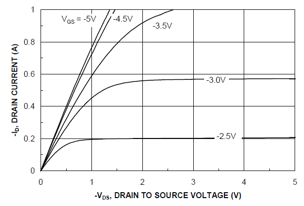
By applying a fixed voltage to the gate of the transistor and ensuring that the transistor is in saturation (\$V_{GS} > V_{TH} \mbox{ and }V_{DS} > V_{GS}-V_{TH}\$), you will create a current reference. Using the I-V curves from the BSS84 PFET you mentioned in your question, you can see the horizontal lines at VGS = -3.0V and VGS = -2.5V. If we were to keep the gate voltage set to -2.5V, then the PFET will source a fairly stable 200mA as long as the transistor is in saturation (\$V_{DS} > 2.5V-1.7V\$).

BSS84 I-V characteristics

If we take two matched FETs, we can connect them in a way that the first FET generates a stable reference voltage for the second FET. This circuit is called a Current Mirror. As with most problems, if the output current is not accurate enough, you can add more transistors, give up some head room, and get a flatter current curve.

Most discrete FETs are not matched well enough for accurate current mirrors, and not all transistors maintain a nice flat ID curve all the way to VDS_MAX. What makes a transistor good for analog/saturation mode circuits is a flat ID curve in saturation. Deep sub-micron transistors have more of a slope to them, and have less ideal performance. Some power transistors are not designed to operate in the saturation region (large power dissipation) so the characteristics there are not so important.

It is often difficult to build two different batches or wafers to have identical parameters (k', Vt, W/L), but matching adjacent devices is much easier. This concept of matching is one of the fundamental concepts of IC fabrication, where the variation between wafers or batches can be large, but the variation between adjacent devices can be very small.

\$\endgroup\$
0
1
\$\begingroup\$

The K factor can be experimentally measured by taking readings of Id and Vgs in the linear region. Matlab tools like curve fitting can be used to determine Vth and K.
You can also use the datasheet curves(ID vs Vgs) and take values from them if dont feel like measuring yourself.

The equations you posted are valid as i have simulated a mosfet turn on process with the equations. Also miller plateau voltage and length was predicted accurately with the above equations. They were accurate to about +-50ns compared with oscilloscope readings.

\$\endgroup\$
0
\$\begingroup\$

MOSFETs are generally designed to have a specific threshold voltage and different kinds do indeed have different uses. When the gate voltage is low and the transistor is turned off, there is a drain current according to: $$ I_D \propto e^{V_{GS} - V_{th}} $$ In saturation, the relationship is approximately: $$ I_D \propto (V_{GS} - V_{th})^2 $$ Increasing the threshold voltage effectively shifts the U-I characteristic, leading to a smaller leakage current when turned off, but also reducing the current flow when the transistor is switched on. There are several difficulties in designing MOSFETs with very specific threshold voltage requirements, this lecture mentions a few, but the need (and use) for highly accurate values is limited, as the parameter is very much temperature dependant.

\$\endgroup\$
0
\$\begingroup\$

MOSFETs can be used as current sources, a Cascode configuration is one example where both BJTs and MOSFETs make good current sources.

\$\endgroup\$

Your Answer

By clicking “Post Your Answer”, you agree to our terms of service and acknowledge you have read our privacy policy.

Not the answer you're looking for? Browse other questions tagged or ask your own question.