It's about efficiency and cost. The trend in the electronics industry for power management devices is to do away with transformers as much as possible (and with it, copper and it's weight). The way they do it legitimately is with a class of circuits generally called switch-mode power supplies (SMPS) and converters.
In switch-mode circuits, an oscillator (usually square-wave, with frequencies ranging from ?20kHz up to the low MHZ in some cases) controls a switch, usually a MOSFET, on/off, which controls an energy storage element, i.e. an inductor or a capacitor, depending on the circuit topology, and there are a few, as you will learn in your ECE course if and when you do an intro power electronics subject.
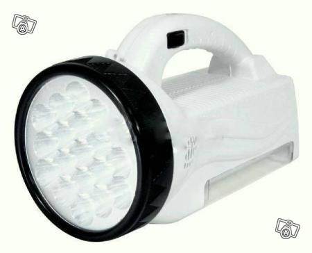
The battery charger you saw is most probably an example of an ACDC buck converter, I hope. (If it isn't, deep six it.) There are also ACAC and DCDC converters. If they step up the primary voltage, they are boost converters. If they step down the primary, they are buck converters. Not to be outdone, there are also buck-boost converters, which, for example, are used to extend the life of batteries in battery-powered circuits, for when the battery voltage reaches below the required supply voltage. (I haven't heard much about boost-buck converters, but I wouldn't be surprised if they have some applications).
One other aspect is the weight saving, and with it the cost of copper. If I can reduce the weight of my device, I can ship more of them at lower cost and higher margins, or add some extra features. As you may know, as signal frequency increases in an inductor, the inductance increases. Hence a trend for some designers to use high oscillation frequencies to reduce the inductor size - compare aerospace power electronics operating at 415 Hz vs the general power grid at 50/60 Hz. However, with increased frequencies come increased losses ("parasitics"), both ohmic and in the \$R_{ds(ON)}\$ parameter in your MOSFET switches, and others. So in power electronics, there are tradeoffs, and lots of them, as you will learn.
Because there is a lot of energy present in switch mode power circuits, and as they are operating at close to the limits of the components' tolerances, they do tend to drift with time (for the chips, look up electromigration, and "physics of failure"). The high energy is what makes these circuits dangerous to work with. Designers use power class components because of these requirements, and they are more expensive, but sturdier, than your run-of-the-mill passive component.
Quite a few semiconductor manufacturers make power and battery management chips, and now energy-harvesting chips, and usually have very good technical literature on the subject, so start exploring.
Welcome to the world of power electronics.
EDIT
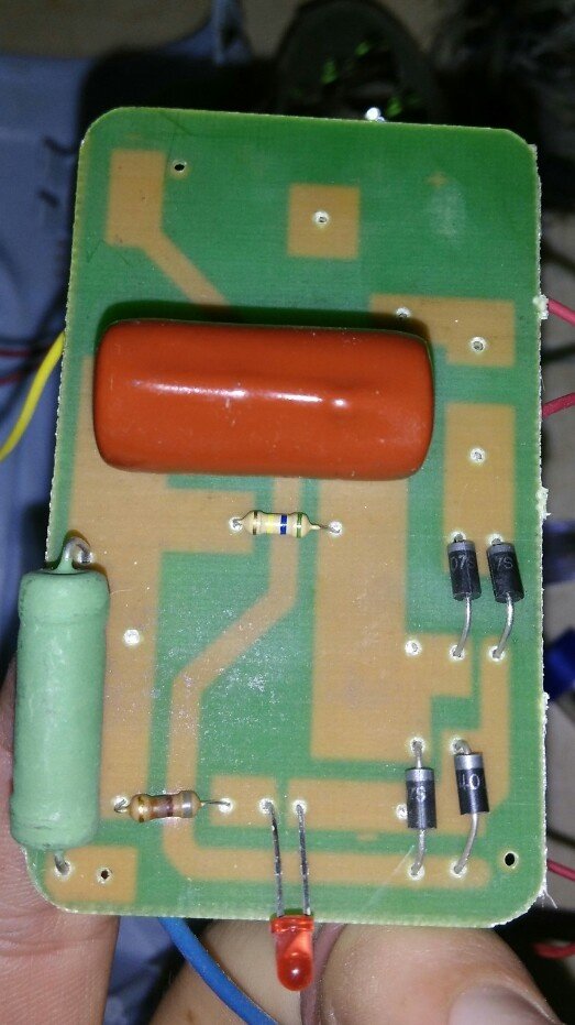
The circuit board you've shown is the way not to do it. If I've read the board correctly, the big green component is most probably a high power, high value wire-wound resistor, which drops the voltage and restricts the current from the mains voltage, then rectifies this still AC voltage and smooths it out with a whopping big capacitor (orange-red component). It will work till the resistor fails. If it fails as an open-circuit, the charger won't work, but if it fails as a short-circuit, it will blow the rectifier diodes and the capacitor. This is not a safe circuit. Take it back and get a refund if you can, or throw it away before someone gets hurt. (Or use it for parts in non-critical projects :-) - the components are likely to be cheap and low quality.)


