4
\$\begingroup\$

I'm trying to learn about electronics, so please bear with me and keep in mind that my idea may be completely nonsensical...

I have this voltage regulator: T317CM

I want to regulate the voltage of a circuit using the digital pinout of a computer board, which is on a separate circuit. If the digital input is high, the voltage of the circuit should be reduced, and if the digital input is low the voltage should be unaffected. Or vice-versa, it doesn't matter. I want a setup something like this:
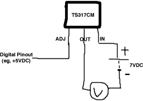
circuit

I can't make any sense of the datasheet, but with a few packs of cells and a multimeter I can reduce 7V to 2V, and keep at 7V if I short two of the pins. If I just make the diagram above the voltmeter always reads 7V, regardless of the pinout voltage. The pinout circuit only connects to the circuit being regulated with that wire - does the ground wire need to be connected somewhere too?

Here's a table of expected inputs/outputs:

V of Digital Pin  |  V in  |  V at voltmeter
       0V             7V            7V
       2V             7V            5V
       5V             7V            2V

These are just rough values and it can be the other way around if that makes the circuit simpler (eg, V at voltmeter = 7V when digital pin is 5V)

\$\endgroup\$
8
  • \$\begingroup\$ What exactly do you want to do? Please provide values for normal voltage (Vnorm = ?) that you are expecting if digital signal is LOW, reduced voltage (Vred = ?) if digital signal is HIGH, and the input voltage (Vin =?) for the regulator. I will modify my answer to help you achieve what you want. \$\endgroup\$
    – shimofuri
    Commented Mar 18, 2012 at 9:38
  • \$\begingroup\$ Vnorm=7V if signal is low, Vred=2V (or the lowest value the regulator can manage) if signal is high. The input voltage, Vin=7V. I think I can vary the voltage of the digital pinout, so if I set it to 2.5V then V should be reduced to around 5V. None of this has to be exact, I just need some way of decreasing the voltage from the pinout. \$\endgroup\$
    – Matt
    Commented Mar 18, 2012 at 9:49
  • \$\begingroup\$ @Matt - The voltage regulator requires a minimum load current. Did you provide a load, or did you measure the output pins without a load? Usually the minimum load current is given by the voltage divider. \$\endgroup\$
    – PetPaulsen
    Commented Mar 18, 2012 at 10:06
  • 1
    \$\begingroup\$ @Matt if you have an analog signal for input, you can simplify things by building an amplifier instead to control the motor which can be accomplished by a single high capacity transistor. In your case, you need to build and inverting amplifier. \$\endgroup\$
    – shimofuri
    Commented Mar 18, 2012 at 10:35
  • 1
    \$\begingroup\$ And where would I learn such datasheet-reading skills? \$\endgroup\$
    – Matt
    Commented Mar 18, 2012 at 11:06

3 Answers 3

5
\$\begingroup\$

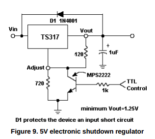
It's probably too late for OP, but I'll give the answer to the actual problem: How can a 317 regulator be switched to a low voltage under control of a digital signal. The answer is actually shown in the linked datasheet:

enter image description here

When the "TTL control" signal is high, the lower resistor in the adjustment divider is effectively shorted, and the output voltage will drop to about 1.2 V (maybe 1.4 V, accounting for the Vce-sat of the transistor).

For a 3.3 V logic signal, the 1k resistor in the base of the transistor may have to be reduced.

If the "reduced" output level needs to be higher than 1.2 V, an extra resistor could be added at the collector of the transistor.

\$\endgroup\$
7
  • \$\begingroup\$ I would expect that with a typical modern strong-drive CMOS output one could probably get by without the transistor. Simply tie a 1K resistor between Vadj and Vout, 470ohm to the processor pin, and 2.5K from the processor pin to ground. \$\endgroup\$
    – supercat
    Commented Jul 31, 2012 at 5:11
  • \$\begingroup\$ @supercat, I think that would give the expected result when the input control signal is low, but for a high control signal (assuming 3.3 V), I calculate the regulator would try to drive to -3 V, which obviously it can't do. What it would actually do is an open question --- I think this pushes into the realm of undefined behavior, or an operating condition not expected by the chip designers. On that basis, I wouldn't want to use that circuit as anything but an experiment. \$\endgroup\$
    – The Photon
    Commented Jul 31, 2012 at 16:10
  • \$\begingroup\$ The 317 does not try to make the Vadj pin sit 1.25 volts above ground, but rather tries to make its output be 1.25 volts above the Vadj pin. Increasing the Vadj voltage will increase the output; with the values I have, Vadj should sit 0.75 volts above the voltage on the CPU pin, and so the output should be 1.25 volts above that. \$\endgroup\$
    – supercat
    Commented Jul 31, 2012 at 16:52
  • \$\begingroup\$ @supercat, You're right of course. Why am I being an idiot? \$\endgroup\$
    – The Photon
    Commented Jul 31, 2012 at 17:11
  • \$\begingroup\$ @supercat, your idea does depend on the ability of the control logic output buffer to sink current when in the high state. This could result in current flow through "unexpected" paths. Not saying it won't work, but would need some careful consideration and it will depend on what exactly is driving the control signal. \$\endgroup\$
    – The Photon
    Commented Jul 31, 2012 at 17:15
3
\$\begingroup\$

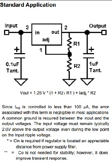
The voltage output of adjustable voltage regulators from the LM317 family is controlled by the current input to the ADJ pin. Typically, the ADJ current is programmed by two resistors (see R1 and R2 in the datasheet) forming a voltage divider.

Please see the schematic for "Digitally Selected Outputs" under "Typical Applications" on page 22 of the LM317 datasheet that can be found here: http://www.ti.com/lit/ds/symlink/lm317-n.pdf

\$\endgroup\$
7
  • \$\begingroup\$ IMO, the voltage is not regulated by the current on the ADJ pin, but by the voltage applied to the ADJ pin. A comperator in the voltage regulator compares the voltage applied to the ADJ pin with the internal voltage reference. \$\endgroup\$
    – PetPaulsen
    Commented Mar 18, 2012 at 9:46
  • \$\begingroup\$ @PetPaulsen that's the assumption that I made when I ordered these, and thought that the resistors were just a convenience for more common circuits. It doesn't seem to work that way though - is my diagram correct? \$\endgroup\$
    – Matt
    Commented Mar 18, 2012 at 9:55
  • \$\begingroup\$ In its typical application, it is programmed by current Iadj. Please see "Application Hints" on page 9. Why current? Because these regulators operate on "floating mode". In fact, you can use it for regulating at higher voltages: national.com/ms/LB/LB-47.pdf \$\endgroup\$
    – shimofuri
    Commented Mar 18, 2012 at 10:02
  • 2
    \$\begingroup\$ NO! - Vout is set to Vadj + 1.2V. This DOES cause varous currents to flow, and you do need a specified minimum Iout BUT the device is fundamentally voltage controlled by the voltage at pin Vadj. \$\endgroup\$
    – Russell McMahon
    Commented Mar 18, 2012 at 11:12
  • 2
    \$\begingroup\$ @RussellMcMahon As the flag koan goes (ralphmag.org/AR/why.html), it is the mind that programs the regulator. ;-) Whether it is current or voltage, Thevenin or Norton, it's all relative. The more convenient wins. \$\endgroup\$
    – shimofuri
    Commented Mar 18, 2012 at 11:25
1
\$\begingroup\$

You say that you cannot understand the datasheet.
The DS has very clear an very specific examples of how to use the part as shown below.
If you cannot understand simple circuits such as this one then you need to learn to do so as it is fundamental to learning the art.

The diagram that you supplied does not make full sense. I and others can guess at what youare trying to show but it is not certain. You would be betteroff taking the correct diagram as shown below and modifying it to convey your point.

To answer your incomplete and implied question:

Rather than using R1 and R2 to set the voltage at Vadj,
if you instead applied a voltage of Vmatt to pin Vadj
and if Vij was connected to a voltage at least 3 volts greater than Vmatt,
then
Vout = Vmatt + 1.25V.

enter image description here

LM317

When

  • Vin < Vinmax (about 40V often) and

  • Vin > ~ 4.5 V and

  • Vin >V_out_desired + 1.25

  • The minimum load requirement from the datasheet is met (usually done by having R1 is some maximum value)

Then Vout = Vadj + 1.25V.

Many of the comments people are making about currents are relevant BUT the above is the LM317s fundamental defining equation.

\$\endgroup\$
1
  • \$\begingroup\$ RE your statement, "if you instead applied a voltage of Vmatt to pin Vadj and if Vij was connected to a voltage at least 3 volts greater than Vmatt, then Vout = Vmatt + 1.25V."; you left out a key requirment: There also must be a feedback path such that if the Vout drifts too high, it will raise the voltage at Vadj and if Vout drifts too low, it will lower the voltage at Vadj \$\endgroup\$
    – The Photon
    Commented Mar 19, 2012 at 2:42

Your Answer

By clicking “Post Your Answer”, you agree to our terms of service and acknowledge you have read our privacy policy.

Not the answer you're looking for? Browse other questions tagged or ask your own question.