1
\$\begingroup\$

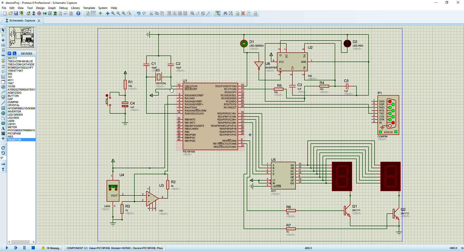
I'm working on a temperature sensor. I've got:

  • LM35 (Sensor)
  • LM741 (Op-amp to amplify LM35 Vout to 5V)
  • PIC 14F458

The temperature is shown on two 7-segment displays with only one BCD converter (4511). Therefore I multiplexed these two displays.

The problem is that my 7-segment displays are flickering a lot and I don't know why.

If you want to see the simulation on Proteus: LM35 - SSD

Here's the schematic diagram on Proteus :

schematic diagram

And here's the C code on CCS.

#include <sonde2.h>
#include <math.h>

#define CONV_CST 0.48875855327
#define TRESHOLD 25
#define TENS_DISPLAY PIN_E0
#define UNITY_DISPLAY PIN_E1
#define GREEN_LED PIN_C0
#define RED_LED PIN_C1


int simpleBCDConverter(value) {
   // Shift tens from 4 bits to the left
   // So we have ([Tens] [Unity]) XXXX XXXX
   return ((value / 10 % 10 << 4) + value % 10);
}

/**
 * Convert a number of 10 bits to its BCD equivalent
 */
void bitsToBCD(int value) {
   int tens = value / 10 % 10;
   int unity = value % 10;

   output_high(TENS_DISPLAY);
   output_d(tens);
   output_low(UNITY_DISPLAY);
   delay_ms(10);

   output_high(UNITY_DISPLAY);
   output_d(unity);
   output_low(TENS_DISPLAY);
   delay_ms(10);


}

/**
 * Check temp level, and switch on the right led
 */
void checkLed(int temp) {
   // If temps is greater than treshold
   // Blinking Red LED with 555 (astable)
   if (temp > TRESHOLD) {
      output_low(GREEN_LED);
      output_high(RED_LED);
   } else { // Otherwise, green LED
      output_high(GREEN_LED);
   }
}

void main()
{
   setup_adc_ports(AN0);
   set_adc_channel(0); // A0 connecté à l'entrée analogique
   setup_adc(ADC_CLOCK_INTERNAL);
   setup_timer_0(RTCC_INTERNAL|RTCC_DIV_1|RTCC_8_BIT); // 51,2 us overflow
   setup_timer_1(T1_INTERNAL|T1_DIV_BY_1); //13,1 ms overflow

   setup_low_volt_detect(FALSE);

   int temperature;

   while(TRUE) {
      //delay_ms(10);
      // Read the value from A/N converter (10bits [0 => 1023])
      // And convert it to a range from 0 to 100 (°C)
      // 0.48 => (5 / 1023) * 100
      temperature = read_adc() * CONV_CST;

      // Check temp level
      checkLed(temperature);

      // Convert bits to BCD
      // And show temp on 7 segment displays
      bitsToBCD(temperature);
   }

}

Thanks.

\$\endgroup\$
2
  • 6
    \$\begingroup\$ This is likely because the simulator is not running at realtime speeds. When you build this in hardware, the digits will alternative fast enough that persistence of vision will cause them to appear as being simultaneously illuminated. In other words, this problem is very likely a case of trusting the simulator too much. Simulators only get you so far... \$\endgroup\$
    – uint128_t
    Commented Feb 19, 2017 at 19:17
  • \$\begingroup\$ Note that this circuit won't work as designed -- you cannot run a 741 op-amp off a 5V supply. \$\endgroup\$
    – user39382
    Commented Feb 20, 2017 at 0:27

2 Answers 2

1
\$\begingroup\$

The problem is that my 7-segment displays are flickering a lot and I don't know why.

run the display routine in a timer isr so it is updated on an fixed interval.

\$\endgroup\$
0
\$\begingroup\$

I would suggest structuring the code this way:

output_d(tens);
output_high(TENS_DISPLAY);
delay_ms(10);
output_low(TENS_DISPLAY);

output_d(unity);
output_high(UNITY_DISPLAY);
delay_ms(10);
output_low(UNITY_DISPLAY);

This makes it more clear how the timing is done (I initially got tricked by this, so my first answer was bogus). This will also ensure both digits get equal time of being lit, intead of one of them also including the processing time, thus making it slightly brighter.

Another suggestion is that you may want to lower those 10 ms delays. They give you 20 ms per complete display, and throw in some time for ADC and processing ... your display will flicker at less than 50 Hz. That might be noticeable. You might want to decrease that to 1 ms. It's a tradeoff depending on how slow the other processing is. If you make the delay too small, most of the time the display would be unlit (during processing), and perceived as lower brightness.

As @uint128_t commented, your simulation speed might be a bit slow, too, but first try the code changes.

\$\endgroup\$
2
  • \$\begingroup\$ The displaying is worse to be honest \$\endgroup\$ Commented Feb 21, 2017 at 7:22
  • \$\begingroup\$ Assuming no other overheads 20ms per update is 50 Hz. That is quite low, and your eye will have very little tolerance for variation before it sees it as a flicker. Updating the display segments at 100 Hz or higher would be better. Use an interrupt routine to do the updates, a simple state machine running off a 1 kHz interrupt could cycle between the digits with each digit getting equal on time, and have little or no time where either digit is not lit. The value reading and digit calculation would happen in a separate thread, likely simply the main loop waiting for the ADC to finish. \$\endgroup\$
    – RBerteig
    Commented Mar 28, 2017 at 0:25

Your Answer

By clicking “Post Your Answer”, you agree to our terms of service and acknowledge you have read our privacy policy.

Not the answer you're looking for? Browse other questions tagged or ask your own question.