3
\$\begingroup\$

I am working on a project where a part of the circuit I have to design is sensing AC with microcontroller. As you can see below this cicruit is meant to operate with resistors, capacitors and an optocoupler.

Here are two designs I have in mind: enter image description here
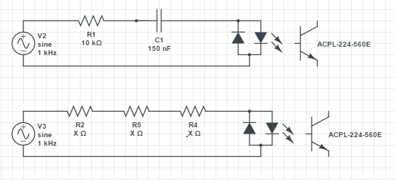
This circuit has to be reliable and last for a good amount of time (at least 5 years). The circuit will run only when the window shutter is moving which means the circuit will be mainly off.

In case I chose first design (preffered because of size limitations) I would use X class capacitor. Final value is yet to be determined.

The most problems I have is with the resistor. When the circuit turns ON / when AC (230 effective, 325 peak) voltage becomes present in the circuit, the current will only be limited by the resistors resistance before capacitors imedance kicks in. This means that the voltage across resistor will approximately be:

enter image description here

where worst case scenario AC ampliude is 325V (or more because of other factors) and Uf (diode forward voltage) will be 1.1V +/- 0.4V.

This means that for a brief moment power dissipated by the resistor will be more than 10.5W. I know that some resistors have graphs showing pulse powers. Should I even take this into account in my example?
I don't really know how long this pulse will last since I don't know how to simulate this, but I really think we are talking milliseconds or even less. Can anyone help me with this problem?

Would second circuit be more reliable than the first one? The heat sholdn't really be an issue since the sensing part of the circuit (which I'm showing here) isn't really supposed to work for long periods of time. Not even in minutes range. But like I said the 1st design is the one I would prefer.

Some additional info:
I've looked over several resistor types. I read MELF resistors are usually good to use where pulses are likely to occur though I would rather use thick film smd resistors which are easier to mount. Resistor will be rated for 400V+ and after the capacitors impedance kicks in the power dissipated by the resistor will be aroun 1W which is quite some power but like I mentioned previously won't be lasting for a long time (I was hoping 1.5W resistor would do the job).

The optocoupler is probably going to be the one shown in the design. Optocouplers absolute maximum ratings: If = +/- 50mA, Ifsm = +/- 1A, I will try to stay in < 10mA range.

Generator frekuency does no reflect actual frequency the circuit will be exposed to. AC mains voltage: 230 effective / 325V peak, frequency: 50Hz

\$\endgroup\$

4 Answers 4

1
\$\begingroup\$

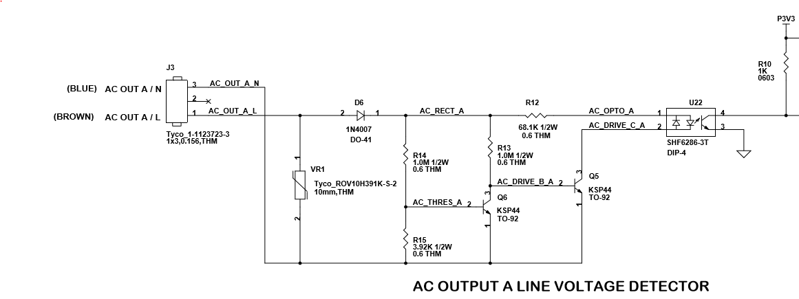
Since you are using an opto-coupler it is clear that you are detecting AC frequency or zero crossing as opposed to detecting the sine wave amplitude through each AC cycle. I have devised a simple reliable circuit that I've used in products that keeps the power level down in the AC detection circuit so there is no need for high power components.

enter image description here

The concept of this circuit is that the current load from the AC line through the opto-coupler is cut off as the AC voltage pulse amplitude gets too high. Thus the circuit generates two pulses (one at the at the leading edge and one at the trailing flank) for each positive AC voltage pulse. It is easy to use a microcontroller to measure the pulse spacing. Leading edge pulse has a longer spacing since last pulse than the time from leading pulse to trailing pulse.

\$\endgroup\$
5
  • \$\begingroup\$ Interesting circuit, do you have to specially select the opto with a high CTR? This does not appear to work if the CTR is less than about 200%. \$\endgroup\$ Commented Feb 23, 2017 at 17:51
  • 1
    \$\begingroup\$ @JackCreasey - Yeah this wants to use an opto-coupler like the part number shown on the schematic. One that works also with minimal forward LED current. You pay a bit more for that type of opto-coupler but the low power dissipation of the circuit keeps overall heat way down. I did this after getting tired of the conventional high power resistors failing and burning the PCB material brown. This circuit works from ~85VACrms to above 240VACrms. \$\endgroup\$ Commented Feb 23, 2017 at 18:44
  • \$\begingroup\$ Your circuit is clever but someone who works with us said that he can't make the code work the way he want's to if it doesn't have a constant high or low value hence why I'm putting these circuits which I am. So you think RC circuit would really be too unreliable for AC main sensing? \$\endgroup\$ Commented Feb 23, 2017 at 19:03
  • \$\begingroup\$ @GalErženPajič - Let me just say that long term circuit reliability tends to be inversely proportional to the amount of power dissipated in the circuit components. \$\endgroup\$ Commented Feb 23, 2017 at 20:51
  • \$\begingroup\$ @GalErženPajič - If the programmer cannot convert the outputs of the circuit that I have shown into an equivalent high/low waveform that corresponds to the AC sine wave's positive and negative peaks then they are a beginner or very junior embedded programmer. It does take some usage of a timer mechanism to make pulse separation timing measurements. \$\endgroup\$ Commented Feb 23, 2017 at 20:55
0
\$\begingroup\$

Go for the first part. The capacitor's impedance will help limit the total current through the branch. If you use a resistor that is not too tiny, it can handle the peak power pulses. Use a capacitor that is rated for 325 V in your case; AC type.

You can use online circuit simulators to reach at the values for the resistor and capacitor if needed.

Issue with the second part:

For 50mA peak current in the branch (assuming no diode drop), you need : 325 / 50e-3 = 6500 Ohm.

Peak power dissipated: (325 ** 2) / 6500 = 16.25 W.

The total power, integrated over the period of sine wave is going to be less but not too less. Look into RMS power.

Thus, you need a resistor that is rated to dissipate that power and you have to keep the surroundings of the resistors open to let the heat dissipate.

Resistors in series (e.g. 6500 / 3) will still collectively dissipate the same amount of power but over a bigger surface area. Thus, you can reduce the rating of each resistor but localized heating is going to be the same.

\$\endgroup\$
2
  • \$\begingroup\$ Sorry I might have not been clear about 50mA current. That is Absolute maximum rating of the optocoupler, I will try to be in the range of 10 or less milliamps. Yes, the pulses is what I'm really concerned about. Was thinking of getting 400V+ rated resistor. What I'm not really sure about is if I even have to consider resistors datasheet regarding pulse power. \$\endgroup\$ Commented Feb 23, 2017 at 16:36
  • 1
    \$\begingroup\$ Use any cheap resistor (0.25W making sure I^2*R is less than 0.25) and you are good to go. They "should" be able to handle 400V. Use a small capacitor that has higher impedance to limit the current. As said before, simulations will help. Ofcourse you can do the calculations as well. \$\endgroup\$
    – nvd
    Commented Feb 23, 2017 at 19:43
0
\$\begingroup\$

Your calculation of the resistor power is in error (for your circuit 1). Even if you assume that the AC is turned on at the very worst possible moment, the RC time constant is low (0.01 s) so the capacitor charges quickly following the AC voltage. The major problem with the first circuit is that your signal is phase shifted, so it's not great as a zero crossing indicator.

The second circuit works ok, and provides a relatively stable reference, but it will be offset from the zero crossing. This is because you need a minimum current to get a signal (through the CTR of the opto) so the indicator is offset. If you want the signal to be closer to the zero crossing you need to lower the value of the resistor, which of course raises the power dissipated.

It surprises me that many folks still design using old established techniques, and not taking advantage of modern silicon solutions.
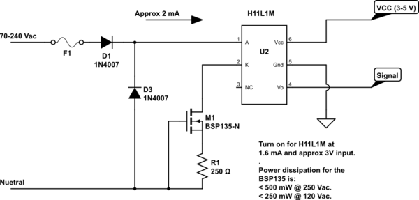
I designed the circuit below (big note: I have not built it yet), which uses a high voltage depletion mode FET as a constant current source (this FET has nice binned characteristics). This allows you to turn on the signal to the microprocessor very close to the zero crossing. The FET replaces the resistors you would normally use and has to handle the power dissipation. However since it's constant current it turns on at a very low threshold voltage.
Here the worst case dissipation is under 0.5 W @ 250 Vac, and it would still provide quite accurate zero crossing indication down to under 20 Vac.

Any comments on the design welcome.

schematic

simulate this circuit – Schematic created using CircuitLab

\$\endgroup\$
0
\$\begingroup\$

Goo with the forest circuit. The capacitor there is essentially a lossless resistor.

For designs like this, the key is to determine the current you need for the opticouplers. And then back calculate the rest of the circuit.

\$\endgroup\$
1
  • \$\begingroup\$ Yes, that is why I would rather use the first one too. But I have no knowledge of what is more reliable in the longer run and the power rating I mentioned about resistor. And the optocoupler current calculation is not really a problem. I really just need the optocoupler to be protected from initial inrush of current - before the impedance kicks in which is done by appropriate resistor. \$\endgroup\$ Commented Feb 26, 2017 at 19:40

Your Answer

By clicking “Post Your Answer”, you agree to our terms of service and acknowledge you have read our privacy policy.

Not the answer you're looking for? Browse other questions tagged or ask your own question.