8
\$\begingroup\$

I'm having a hard time conceptualizing what/how things are working in a voltage divider setup. I've read a couple other questions/explanations where the answerer has said to "not think about it in terms of water", but it's difficult to not do so, to some extent.

What I don't get is how the electricity changes/adapts after the FIRST resistor based on the ratio between it and the SECOND resistor? I know it's in the arena of having to do with "pressures" and pipes, but if you have a resistance further up in the chain of flow, conceptually how does it matter what the resistance is further down the pipe?

And stepping outside voltage dividers (but still in the realm of the question of voltage drop and ratios) -- how/why does ALL the voltage get dropped over a resistor in a one-resistor circuit, but with 2+ resistors/loads, the electrons "know" to somehow ration the voltage drops proportionally? (Obviously I know the electrons aren't consciously working this out and making decisions). Why isn't a voltage drop static over a static resistance/load? Why does it depend on the other resistors/loads in the circuit?

(I don't mind technical, but if possible, please at least add some type of visual conception or demonstration, if you may! :) Thanks!

\$\endgroup\$
0

8 Answers 8

17
\$\begingroup\$

Let's do another thought-experiment:

Imagine that we gradually shorten the connection between the two resistors until it is infinitesimally small. Now you effectively have one resistor with the divider-point somewhere in the middle. One end of this resistor is connected to the supply voltage, let's say 5 Volts. The other end is connected to ground, which we'll call 0 Volts because we'll use it as the reference point for our voltage measurement.

Again, imagine that we gradually move the divider-point up toward the 5V end or down toward the 0V end. At what location along this combined resistor would you expect the measured voltage to drop from 5 Volts to 0 Volts?

Is it clear that the voltage doesn't have a step change at one point, but is proportional to the fraction of the resistor below the divider-point? Voltage drop is linear along the length of the combined resistance.

Now imagine that we gradually restore the length of that connection we stretched in the first visualization. And imagine that the connection itself has no resistance - zero. (It's not quite zero, but it's so close that we can ignore it). Is it clear that the voltage will be no different at either end of the connection as you stretch it out again?

The total voltage drops linearly over the total resistance, and the divider point "samples" that voltage at a specific part of the total.

The current doesn't "care" or "know" whether is flowing through many individual resistors, or one continuous one; the voltage drops continuously along each segment of the resistance path. The "zero resistance" connections just don't matter.

\$\endgroup\$
0
12
\$\begingroup\$

As far as the current is concerned there is no divider, there's only one path which has a certain (total) resistance. Let's say you have a 1k\$\Omega\$ and a 2k\$\Omega\$ resistor in series. Total: 3k\$\Omega\$, and if you apply 3V across it you get, per Ohm's Law

\$ I = \dfrac{V}{R} = \dfrac{3V}{3k\Omega} = 1mA \$

Now Ohm's Law also applies to any individual resistor in the chain. To find the voltage across the 1k\$\Omega\$ resistor:

\$ V = I \cdot R = 1mA \cdot 1k\Omega = 1V \$

So indeed you get a fraction of the original 3V, that's why it's called a divider, whose ratio is defined by the ratio between the resistors. But for the current there's no difference between a load of 3k\$\Omega\$ and one composed of a 1k\$\Omega\$ plus a 2k\$\Omega\$ resistor.

\$\endgroup\$
1
  • 2
    \$\begingroup\$ Wow, what an "aha moment". I've fully understood how to use voltage dividers for a long time, but never thought about why they work... and it seems so damn obvious now! \$\endgroup\$
    – exscape
    Commented Apr 6, 2012 at 15:04
5
\$\begingroup\$

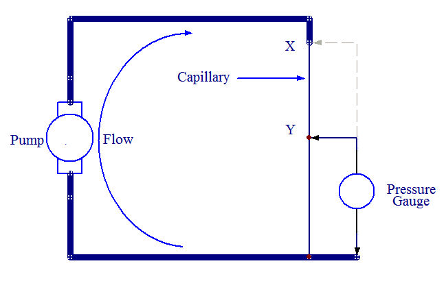
What's wrong with thinking of the water analogy? With a pump pushing water through a capillary, the pressure gauge below will see the full pressure at point X, but about half the pressure at point Y. The water doesn't 'know' what pressure to be at, it just encounters less resistance as it travels down the capillary and the pressure reduces in proportion.

enter image description here

(This is, incidently, how the bypass valve in a domestic central heating system controls the flow rate through the radiators).

\$\endgroup\$
2
  • \$\begingroup\$ While it may be correct, I don't find this analogy easier to understand then electricity. I think that it works to explain the principle, but more than that it only becomes confusing to me. \$\endgroup\$
    – clabacchio
    Commented Mar 29, 2012 at 12:09
  • \$\begingroup\$ @clabacchio - I agree that some people like the analogy and some people don't - it is a matter of personal preference I suppose. I just thought I would point-out that the analogy still holds - even for potential dividers. \$\endgroup\$
    – MikeJ-UK
    Commented Mar 29, 2012 at 12:24
2
\$\begingroup\$

The picture is this: The electrons are pushed along by a force. The total amount of force (supply voltage) gets divided between the amount of resistance in each part of the track. The flow of electrons balances itself in a way so the sum of all voltages on all elements add up to the supply voltage.

Explanation: Current is basically "all electrons in the wire moving slowly in a direction". Imagine a bunch of balls in a hose. One has to exit the other side when you press one in on your side.

To make them move, you have to exert a force. This is an electric force, which is when an electric field (a Voltage basically) acts on charged things, the electrons in our case.

To make them move faster, you have to exert more force. (or rather, the same force more often)

How much force is needed relative to the speed / current, depends on the resistance of the path.

All the electrons in the path are moving along. Meaning all, in the power source, wires, and resistors, all electrons, are moving more or less in unison.

Now the electrons are moving. For each infinitesimal part of the path, there is a resistance, which determines how big a voltage has to be present to make the electrons move along. They do move along, because there is a current. They are forced to.

The voltages of each part of the path add up to the total voltage.

\$\endgroup\$
2
\$\begingroup\$

It's all about Ohm's law.

A voltage over the two resistors creates a current flowing into both of them. This current will be the same for all the resistors, if they're connected in series, and will be given by Ohm's law.

On each resistor, the flowing current will induce a voltage drop, again given by mr O's law.

You can find the math everywhere, but first understand this and how a resistor works. Since it's an abused topic, I would prefer to suggest you reading wiki about the resistor and Ohm's law. Once you understand both, the voltage divider will be magically clear.

Anyway:

How does the electricity “know” the ratio of the resistance in a voltage divider?

How do you know that if you jump down from a bridge, you fall at a certain speed? It's just due to physics.

\$\endgroup\$
1
\$\begingroup\$

Well, first off is the view with one resistor. We'll look at this with a car battery setup and say we've got negative ground and a +12v hot.

In our first circuit, we move 12 volts across 12 ohms of resistance and move 1 amp for 12 watts across our load. That is everything that can move there. The relative difference between the supply and receiving end is the same.

You could view this also as a +6v hot and -6v ground and the circuit would act exactly the same. Upping your supply (hot) or lowering your sink (ground) will create a difference in potential (voltage).

Now, let's change our load: two resistors of 6 ohms each. Our total resistance is now 12 ohms again, so we'll still draw 1 amp. Each load is now consuming half of that: 6 watts. To consume 6 watts across a 6 ohm resistor with 1 amp of power, you must lose 6 volts. Remember, current stays constant in a circuit wherever you measure it. That's why a fuse is effective anywhere in a series circuit. Remember that amperage is basically flow (gallons per minute), and the power derived is a combination of flow and pressure (voltage). Thus, voltage * amperage == watts (motive power).

So that's the electrical part. To use a water analogy, you have to think of the plumbing system a little bit differently. The "sink" where water flows to now has to be regarded as pressurized, so supplying some back-pressure. The loads are turbines in the pipe. If our supply is 100 psi and our sink is 50 psi, we'll get flow.

The pressure difference between two points on the pipe that is after the load is going to be negligibly small. It will still have pressure against the outside world, but the relative pressure when referenced against our 50 psi sink tank will be very low. Adding a split with lots of pipes after the last load won't change it.

If we put in a pipe before the first load and hook it up after the last load, we'll see 100 psi on it... or 50 psi relative to our two tanks. If we tap in the middle of those two equal turbines to our sink, we'll see 25 psi of pressure. The water had to expend some energy to get through the first turbine.

As long as we have enough pressure (voltage) to spin a turbine (drive a load), we will see a drop across that turbine equal to difference in pressure on either side. If we put multiple turbines in there, we'll see a pressure drop that is proportional to the amount of effort it took to spin the turbine.

Remember that voltage and pressure both relate to relative reference. After all, 0psi on the ground is usually measured relatively, and is actually 14.7 psi(absolute). So, pretend for a second that your supply circuit is +24v hot to a +12v ground, and it might possibly make more sense because you'll visualize some back pressure in your head and really focus on the fact that relative pressure is the driving point.

We create more power draw across our turbines by using bigger pipe and bigger turbines with the same pressure, or we can up the pressure on the current pipes. However, the pressure drop across our turbines will always remain in proportion as long as water can flow.

\$\endgroup\$
2
  • \$\begingroup\$ You removed a substantial part, now the first paragraph is impossible to understand \$\endgroup\$
    – clabacchio
    Commented Mar 29, 2012 at 15:28
  • \$\begingroup\$ @clabacchio Eep! thanks for the notice. Seemed to have missed a lot in my copy / edit in vim / paste back... \$\endgroup\$ Commented Mar 29, 2012 at 16:41
0
\$\begingroup\$

It's all in the electrical field. So if we have a circuit with two resistors and we connect a battery, an electric field then appears going from one end of the battery, to the other end through the two resistors. This is the part that travels at the speed of light (in the material). This field is affected by the material of the wire and of the resistance, and also the width of the path, etc. Therefore, the strength of the field at different points is all controlled by the resistance. The electrons in the material then react to the field. The rate at which they move is controlled by the strength of the field, and this is set by the values of the resistances. So the electrons move at the rate predicted because the field that is controlling them, is itself controlled by the resistors. And the field is affected the by the resistances almost instantly, as it's moving at the speed of light, unlike the slow moving electrons.

Hope this is what you were looking for,

\$\endgroup\$
-3
\$\begingroup\$

I also like to think of it in a water analogy, but an easier one. It works like this:

Think of a pipe, where the diameters of different sections is different. The bigger the diameter, the more water can flow. Higher valued resistances will work like smaller diameter pipes, letting less water flow.

Say you have 2 resistances: 1k and 2k. The 2k resistance "pipe" is about half the diameter of the 1k resistance "pipe". If you provide a nice escape for water between them (that is, the divided voltage line), a lot of water will go through it but not all. Some of the water will still go through the 1k "pipe", as there is room in it if it's empty. How much? approximately 1/3 of the water will be able to use the 1k pipe in the same amount of time that 2/3 is escaping through the voltage dividing pipe. So in terms of potential, you will have approximately 2/3V going through the divider. It all depends on how much water gets in (because of the first resistance) and how much water can get out to ground (because of the second resistance).

It will end up being full potential at the two ends anyway, because that's mandatory, but in the middle you'll have the potential that was able to escape through this route, which was way more tempting than the other route.

I'm not sure if the analogy is 100% accurate, but this is a mental model... it doesn't really need to be accurate, just expressive :)

\$\endgroup\$
4
  • \$\begingroup\$ Uhm, the idea of the "escape" looks like an output current that will change the current balance and so the voltage division...try to double-check it \$\endgroup\$
    – clabacchio
    Commented Apr 6, 2012 at 14:35
  • 1
    \$\begingroup\$ Your model requires that water can escape between the two pipes, which for a voltage divider isn't necessary. So your water model doesn't agree with the electrical divider. \$\endgroup\$
    – stevenvh
    Commented Apr 6, 2012 at 14:35
  • \$\begingroup\$ If the 1k pipe is thicker than the 2k, then why do you have to let water escape after the 2k pipe? As you say the 1k pipe can handle everything that passes through the 2k, and more. \$\endgroup\$ Commented Apr 6, 2012 at 15:54
  • \$\begingroup\$ You guys didn't like my model, y get it :). I meant a 1k, then an escape line in a junction, then 2k like this: --¦~~ (where - is 1k, ~ is 2k and ¦ is perpendicular to those). Water enters - with a certain pressure, some of it escapes through ¦ and some through ~. clabacchio's concern is very valid, though... in my model there's less pressure at the end of 2k than there was at the other end of 1k, which is not how it works. \$\endgroup\$
    – gouky
    Commented Apr 8, 2012 at 0:46

Your Answer

By clicking “Post Your Answer”, you agree to our terms of service and acknowledge you have read our privacy policy.

Not the answer you're looking for? Browse other questions tagged or ask your own question.