0
\$\begingroup\$

I'm building a circuit to slowly fade in (when switched on) and slowly fade out (when turned off) two LED bulbs.

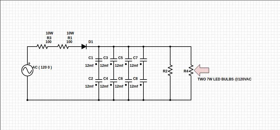
The circuit works, but the two 100 Ohm resistors (see picture) are getting very hot (too hot to touch, but not smoking)

I've had a bit of trouble going about his circuit. I'm rubbish with AC analysis, and not that great with DC. I know the hazards I'm presenting, so besides that, I was hoping someone could point me towards a solution.

I would use the proper sized caps, instead of the series/parallel config, but these were laying around. Also, 100 Ohm 10W resistors were the best I could find at the local Radio Shack.

Basically, I approached this as a DC circuit, since everything past the half-bridge rectifier diode is DC with the smoothing capacitors. Each capacitor is rated at 63V. I'm well within each capacitors voltage handling. I started by assuming (wrongly perhaps) that the bulbs in parallel would be equivalent to around 1029 Ohms, given these are off the shelf, household bulbs rated at 7W, using Ohm's Law at 120V DC. Then calculated the voltage drop for the two 100 Ohm resistors, which should be around 19.5V with a total power dissipation of 1.9W with .1A through the circuit. The fact that the two 10W resistors are so hot, leads me to believe I'm missing something here. I figured they would exceed their power handling during the initial charge of the caps, but would cool off once the caps were charged. What am I missing?

Also, I should add: Once voltage reaches ~40V across the caps, the bulbs start dim and get brighter until voltage level is ~90V across the caps. It takes about 10 seconds to fully charge. My question, is what should the power dissipation be across the two 100 Ohm resistors before the diode?

The bulbs are represented with resistors here. I didn't see a basic LED on Partsim.... enter image description here
Any help would be much appreciated. Thanks!

\$\endgroup\$
11
  • \$\begingroup\$ LEDs are not ohmic, they're current driven. \$\endgroup\$
    – Dampmaskin
    Commented Mar 1, 2017 at 2:27
  • \$\begingroup\$ @Dampmaskin They are not LEDs, but 110 VAC LED light bulbs. \$\endgroup\$ Commented Mar 1, 2017 at 3:05
  • \$\begingroup\$ The current is still flowing through the light bulbs. Where would the light bulb get their current if nothing flowed through the resistors? \$\endgroup\$ Commented Mar 1, 2017 at 3:14
  • 1
    \$\begingroup\$ You need a phase controlled triac which switches the voltage off and on, not a linear lossy pot. But since the Bulb has a constant current range it will not dim until below its regulating range and defined as "dimmable" to prevent internal current stresses. \$\endgroup\$
    – D.A.S.
    Commented Mar 1, 2017 at 3:18
  • \$\begingroup\$ @Dampmaskin You are right, but like Misunderstood said, they are LED bulbs, each with their own rectifying circuit. Surely those (the bulb) have a load resistance. \$\endgroup\$
    – user121798
    Commented Mar 1, 2017 at 3:19

2 Answers 2

1
\$\begingroup\$

It is non-trivial to calculate the power dissipated in the resistors. The input is 120 AC with a peak voltage of ~170V.

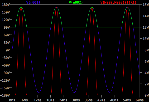
With the voltage at the capacitor being 90V the drop across the resistors is a truncated sine wave with a peak of about 80V.

The easiest way to calculate the power dissipation is to use a free simulator such as LTSpice.

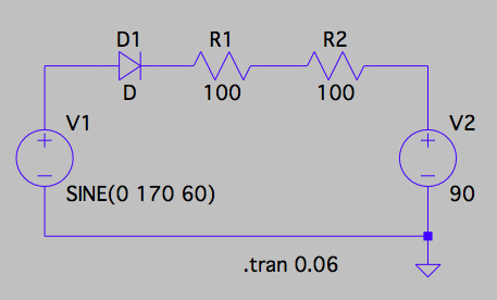
I changed the order of the diode and resistors to make probing the voltages easier but it won't make any difference to the results.

I used a voltage source instead of the capacitor and resistor to speed-up the simulation - it was taking ages to reach 90v.

Schematic

In the plot shown the Blue trace is the incoming AC, Green is the voltage at the diode output and the red trace is the instantaneous power in each resistors, note that it peaks at about 15W.

LTSpice then did the average of the power plot to give 2.9W in each resistor.

Simulation

\$\endgroup\$
2
  • \$\begingroup\$ That's great! Thank you for providing that. I will check out LTSpice. Looks like a great sim tool. Your results aren't too far off from what I am seeing. This still makes me wonder why the 10W resistors are getting so hot. At a 1/4 of their power rating, I would think they would be running fairly cool. \$\endgroup\$
    – user121798
    Commented Mar 1, 2017 at 5:00
  • \$\begingroup\$ Power rating is the maximum power you can safely dissipate within the resistor. The actual temperature it reaches depends on the actual power you dissipate and the amount of heat the resistor can lose through conduction, convection and radiation. They're two different things. \$\endgroup\$
    – Finbarr
    Commented Mar 1, 2017 at 9:41
0
\$\begingroup\$

Kevin White's answer is THE answer, but you have not thought through what happens when power is pulsed. I would do this as a comment, but it is too long.

The issue is that, when power is pulsed, the overall power goes up very quickly as the pulse duty cycle goes down.

Consider a resistor of 1 ohm being driven by a DC 1 volt. Average current is 1 amp. Power dissipated by the resistor is 1 watt, right? Square of the voltage divided by resistance.

Now consider the same resistor being driven by a 10 volt source which is active for 10% of the time. Let's say 1 second on, 9 seconds off. Current is 10 amps for 1 second, zero for 9 seconds, so the average current is 1 amp. With me so far? Now look at power. The power dissipated is 100 watts for 1 second, zero for 9, for an average of 10 watts. So, for the same average current the average pulsed power is 10 times greater.

Apply this to your circuit. With a set of big capacitors, and a corresponding slow rise in output voltage, it's clear that the average current will behave something like your calculations. However, the current through the 100 ohm resistors, as shown on the sim, is a series of shortish pulses, so the power dissipated by the resistors will be much greater than what a DC analysis would lead you to expect.

\$\endgroup\$

Your Answer

By clicking “Post Your Answer”, you agree to our terms of service and acknowledge you have read our privacy policy.