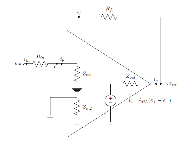
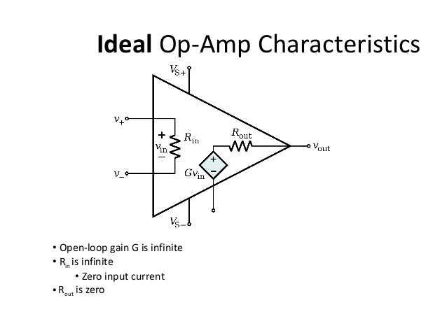
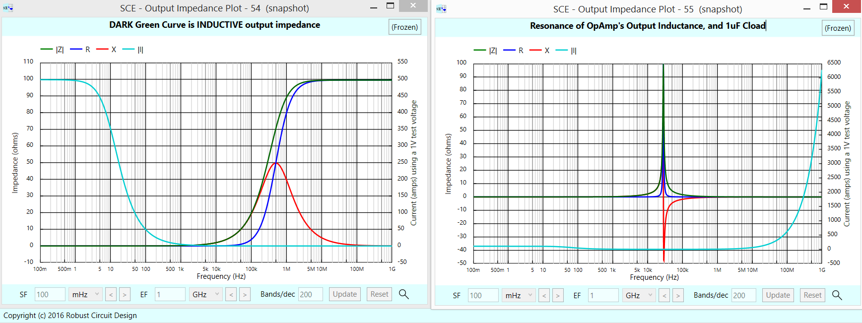
The output current of an OpAmp provides surprises. Over much of the useful range of frequencies, there is a 90 degree phaseshift between Vin (the difference between Vin+ and VIn-) and the Vout. You can see this phaseshift, in the left plot shown below.
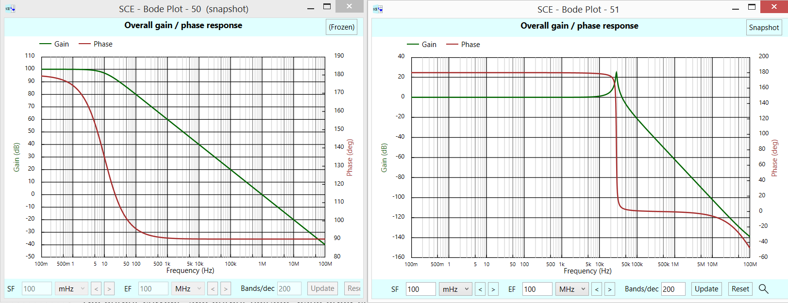 What does this phaseshift do? It makes the Vout appear inductive, particularly with the output current dropping with frequency.
Add on a capacitor, and you get another surprise: peaking of frequency response, shown above in the right plot.
In this next set of plots, we see the OpAmps INDUCTIVE Zout on left (looking back into the OpAmp stage); then we look back into the Cload stage and see the combined effect with the sharp resonance of Lout and Cload.
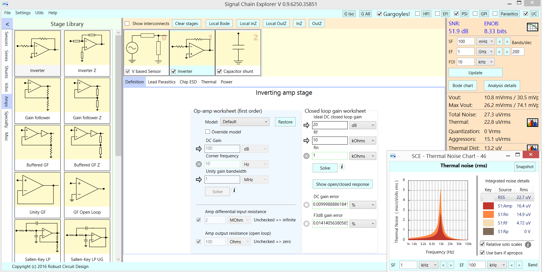
The output current, and output voltage, have other surprises: thermal noise and power supply (deterministic) noise. Those cause a wiggling of the output, even when Vin is fixed. In this next screenshot, look on the lower right, to read
the error from ThermalNoise and from Aggressors (the only activated Aggressor is PSI --- power supply interferer --- show in topright checkbox). Notice the 22.8uV of Thermal Noise and the 15uV of (60Hz, 120Hz) Power Supply noise.
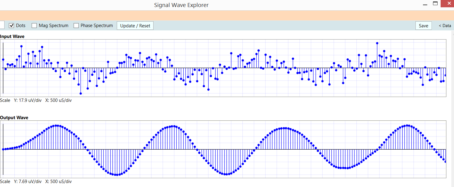
Here is what a 25uV peak signal, at 200Hz, with added 1:1 (0dB) noise power and signal noise, into a 200Hz LC filter. Notice most of the OpAmp noise is gone; we see some wandering of the sinusoid and some "distortion" which is just the noise not being totally removed so that energy upsets the sinusoid shape.
 The Operational Amplifier is very useful, on PCBs or on silicon, but the physics, and math, involved are worth learning so you do not expect too much yet can get excellent performance.
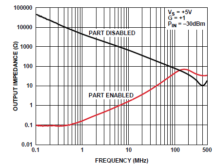
Here is a plot of Zout versus frequency, for an opamp with UGBW of 100MHz. The plot is particularly interesting because the opamp has a ChipSelect pin, thus we see Zout with output transistors controlling the output pin and with those transistors disabled. Up near 500MHz, the Zout nears 30 Ohms, which is impedance of 10pF. Also note the dip in impedance; 10pF and 10nH (Vout pin and VDD pin inductances) resonate at 500MHz.
I'm thinking the 30 ohms Zout is the NPN reac in parallel with PNP reac, where reac is 0.026/Ie_ma thus 0.5ma produces 52 ohms in both emitters, which in parallel become 26 ohms.
