1
\$\begingroup\$

Okay so I haven't had any luck finding an answer on here that I was able to understand (I'm in a BioE program, just dabbling on the electrical side for a project). Overall its a pretty simple circuit I am making.

Here's what I am trying to accomplish:

  • Use Arduino code as a switch to control the on/off power of 4 vibrating motors, which will be wired in parallel (specs: https://www.adafruit.com/product/1201)

  • Motors are powered by an external 9V battery

  • I want to have around 4.5V across the vibrating motors, which I got with a 50 Ohm resistor in series with the 4 motors in parallel
  • Current draw by each motor at 4.5V will be ~90 mA

Here's what I think might work:

  • Need to use a transistor between the 9V (collector) and the (50 Ohm resistor + motors) (emitter)

  • I would use the Arduino Uno digital output Pin 3 (PWM output) and connect it to the "base" of the transistor

Question:

First off, do I have the right idea here?

Lastly, I have never worked with transistors before, how do I figure out which transistor will be correct for this application? i.e. what calculations do I need to make?

Thanks!

\$\endgroup\$
1
  • 1
    \$\begingroup\$ Please keep in mind that 9Volt batteries won't provide power for very long. They typically only provide a few hundred milliAmpere hours. At the rate you are planning to draw current from them, you shouldn't expect more than an hour or two of operation. \$\endgroup\$
    – JRE
    Commented Apr 17, 2017 at 9:28

1 Answer 1

4
\$\begingroup\$

Typically you want a simple low side NPN switch setup. A high side switch would complicate things as your arduino cannot accept higher than 5v at it's input pins (or whatever VCC is).

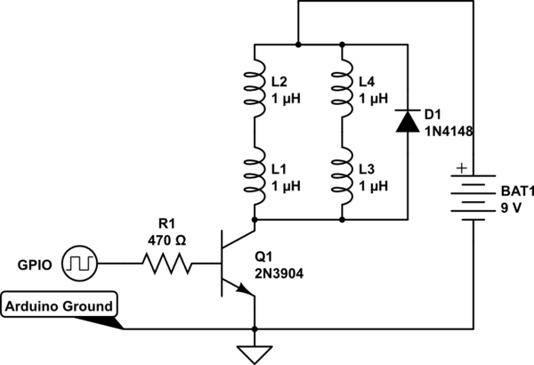
A NPN like the 2n3904 or 2n2222 is all you need. Common workhorses for small signal. You know your target load of 360 ma, and they both have a worst case gain of 30. You would connect the 9V to your motor and the motor to the collector and the emitter to the common ground between your arduino and the 9V battery.

You would connect the base to your gpio with the appropriate base resistor. 470 ohms should do nicely for the base current needed.

As a suggestion, you are wasting half your power in the 50 ohm resistor. As you are turning all of them on with a single pin, you should be able to sixtuplicate your battery life by putting the motors in series pairs without any resistors. Two motors in series should equally divide the input voltage between them.

Additionally, a diode being used as a flyback protection diode across the motors would be ideal, as suggested by SP.

schematic

simulate this circuit – Schematic created using CircuitLab

\$\endgroup\$

Your Answer

By clicking “Post Your Answer”, you agree to our terms of service and acknowledge you have read our privacy policy.

Not the answer you're looking for? Browse other questions tagged or ask your own question.