0
\$\begingroup\$

(I've searched these forums and the web and can't find anything that helps, so I apologize if I've missed something.)

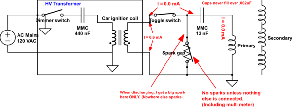
I'm working on my first Tesla coil and am at a loss. This is what I've got going on. See the annotations in the diagram for descriptions of what I've found so far.

schematic

simulate this circuit – Schematic created using CircuitLab

My first guess is that I've got a problem with the current being too low, but then again, it could be something totally different.

(Also, I started with an NST, but it had GFCI and I can't find a non-GFCI anywhere.)

Thanks in advance!

Updates:
- People had questions about the switch. I was using the switch to require two stages of activation, so that someone doesn't accidentally bump one switch and set the thing off. Switch has been removed.
- All grounds have been removed.
- Spark goes a bit over 1cm.
- A photo of the layout (below). Note: This is NOT where I use it. I had to put it away and just pulled it out long enough to lay things out for you to see how it looks.
This is NOT where I use it.  I had to put it away and just pulled it out long enough to lay things out for you to see how it looks.
Once I get it functional, I'm going to lay everything out very neatly and solder all connections.

\$\endgroup\$
5
  • 1
    \$\begingroup\$ What the heck are you using a toggle switch on the high voltage side for? That's just a stupid idea altogether. This schematic is a mess and does not convey any useful information. Please redraw it. There should not be a ground on the input to the dimmer switch. The primary coil should also not be grounded. \$\endgroup\$
    – DerStrom8
    Commented Apr 22, 2017 at 0:32
  • \$\begingroup\$ Some light-dimmers may filter the sharp AC transitions, and so not work. Here's an old project from Radio Electronics, provide your own triac circuit to drive an ignition coil: learningelectronics.net/VA3AVR/circ/hv/l-bulb/l-bulb.html Note that they use 2uF for their AC ballast capacitor, not 0.44uF. WARNING: when it starts working, it may destroy any multimeter connected to the HV side. DMM isn't rated for measuring many-KVs signals! \$\endgroup\$
    – wbeaty
    Commented Apr 22, 2017 at 3:44
  • 1
    \$\begingroup\$ Under what conditions do you have 12kV? Across the spark gap with the MMC connected? \$\endgroup\$
    – Neil_UK
    Commented Apr 22, 2017 at 5:28
  • \$\begingroup\$ How wide is your spark gap? 12kV can generally only jump ~1cm max \$\endgroup\$
    – DerStrom8
    Commented Apr 22, 2017 at 11:24
  • \$\begingroup\$ Updated the post with more info. DerStrom8: It wouldn't let me add my actual drawn schematic, so I was working with the cruddy tool in here. Also, the purpose of the switch was to require an extra step to turn the thing on. (Step 1: flip the HV switch, step 2: get clear, step 3: flip the dimmer switch on the transformer.) @wbeaty: Thanks! That's great info and I'll check out that project as soon as I get a chance. Neil_UK: across the spark gap with nothing else connected at all. Attaching the MMC kills it so it won't even jump a paper's width. \$\endgroup\$ Commented Apr 23, 2017 at 23:31

3 Answers 3

1
\$\begingroup\$

A car ignition coil is far too small output current to be loaded by a 13nF MMC. As you mention, even a multimeter drags the output down.

Usually we use a Neon Sign Transformer (NST) with 10s of mA output current in this sort of setup. I notice you started with NST, which explains a lot! If you hired a U-Haul trailer, then found your car didn't have a tow-ball, would you tie it with string to your bicycle? You need a car for the trailer, you need an NST for 13nF. You have the reasons written on your diagram, coil output \$600\mu A\$.

If you want to continue with an iggy coil, then suggest you rectify the output so it can take its time to charge the capacitor to a high enough voltage for a decent spark. DC coils can work, though a rotary spark gap (RSG) is often necessary for extinguishing the arc after firing. Otherwise, tune the MMC down to work with the iggy coil. Either way, you need to change the design.

Unfortunately GFI-less NST's are becoming rarer, they're not being made these days. But that's what you need to make an unfussy TC that will just work.

SO is a very general forum, Tesla coiling has a very small active community. You would be far better off asking these questions on a dedicated TC forum, you'd get a much better signal to noise ratio. Start with the pupman lists (archive) or 4HV (active) for instance, where you can find the community that has the stuff, and the domain knowledge.

\$\endgroup\$
1
  • \$\begingroup\$ Yeah, I didn't realize that the ignition coil would produce so little current when I built it. I'll continue to keep my eyes peeled for an elusive GFI-less NST and will also try a smaller cap to see if that does anything (at least for starters). I'll go check out 4HV as well, as it's an active forum. Thanks! \$\endgroup\$ Commented Apr 23, 2017 at 23:41
0
\$\begingroup\$

Arcs like to start where there is a so-called corona. A corona is like a one-sided arc: it emanates from a single place - and this will be from a point of high voltage, particularly from a sharp point. This is why Van Den Graaff generators use spherical poles: to reduce corona and risk of arcing. So: reduce sharp edges everywhere but on the spark gap.

This will have a second benefit: a corona leaks current. So reducing sharp edges everywhere but the spark gap prevents unwanted current loss and so reserves more for the arc where you want it.

What size arc do you want? A very rough guide is 1kV required per mm gap. If you really are generating 10kV then I'd be very surprised if you don't get a spark over a few mm. It might also be helpful to measure what current output you get when you short the output of the coil with an oscilloscope in parallel with a small resistor, so acting as an ammeter. The higher the current it can output, the greater the spark. (And the more dangerous!)

Also remember that at very high voltages, what would normally be considered an insulator actually becomes a relatively good conductor. Insulation with 10MOhm resistance across 10kV will be carrying 1mA! (Meaning 10 watts disappears into your insulation. To reduce this, try operating in dryer air, use the best insulators you can, ensure greatest path between conductors, and ensure all paths are clean, eg to stop grime conducting.

Also, consider unwanted capacitances: at high frequencies (including sharp pulses) a small capacitance between conductors can absorb AC power.

Also, consider that many components are not ideal. Your capacitor will leak. Any stored voltage will leak DC current between the plates. Choice of capacitor will be crucial; check its data's heat for specs. Your diagram says the cap never exceeds 0.02uF - this is non sensical since a capacitor's value is fixed! 10nF capacitors will always be 10nF, nothing else.

How are you measuring current in your circuit? Why do you have the toggle switch? I bet this is arcing since I have rarely seen toggle switches that are designed for more than mains voltage! Very dangerous too, I wouldn't put my finger anywhere near that. Where did you get your circuit from? I'm also wondering if there should be a diode somewhere.

If you want more help on this in the future, more details would help: pictures, specifics of your layout - at such high voltages, such things are crucial, unlike for low voltage circuits.
\$\endgroup\$
2
  • \$\begingroup\$ You mean "it emanates", not "it Emirates"! Autocorrect, I would imagine. \$\endgroup\$
    – Hearth
    Commented Apr 21, 2017 at 22:46
  • \$\begingroup\$ The OP is asking in a general forum about a very specific technology, for which there is very specific guidance. Your answer comes from the general side and shows no knowledge of the specifics. While the general advice is not wrong, it's not really applicable to the OP's situation. He's taken a 'build this and it works' schematic, then changed one component (NST) to one with a totally different capability (iggy coil). Dry air, sharp points, applicable to VDGs certainly. \$\endgroup\$
    – Neil_UK
    Commented Apr 22, 2017 at 5:34
0
\$\begingroup\$

Welcome to the world of coiling. I was there once years ago with the frustration as you maybe feeling. Dont give up trying.

First thing is that your spark gap is in the wrong place it should be in line with your mmc.

Second, the corona is a current leak though that maybe fixed by moving components far enouph away from each other and making sure they are insulated.

Also your mmc is to close to the primary. Have you tuned your tc. Its unlikely that a tc will work if you havent tuned the primary with the secondary or made sure that you have the correct sized mmc for the power supply.

I recommend Javatc, its a tc simulator where you plug in parameters and it will run the sim and give you what needs to be changed in your design. But your on the right track. Oh and you may want to place one end of your spark gap on the other side of the mmc and get rid of that toggle switch

\$\endgroup\$

Your Answer

By clicking “Post Your Answer”, you agree to our terms of service and acknowledge you have read our privacy policy.

Not the answer you're looking for? Browse other questions tagged or ask your own question.