58
\$\begingroup\$

There is no dedicated GND in the classical Ethernet 8P8C ("RJ45") pinout.[1]

Why does the Ethernet spec not include a ground, unlike many other cable types used for interconnecting devices that may both have its independent power source as well, e.g. RS-232 or USB?

\$\endgroup\$
17
  • 16
    \$\begingroup\$ And note that all signals are differential. This might tell you something ;) \$\endgroup\$ Commented May 4, 2017 at 7:09
  • 9
    \$\begingroup\$ rs232 is referenced to ground, usb carries power, ground and a diff signal yes, but not relevant here. Ethernet is meant to run hundreds of feet, that is another clue. \$\endgroup\$
    – old_timer
    Commented May 4, 2017 at 11:13
  • 7
    \$\begingroup\$ @mykhal USB does but RS-232 doesn't. You may rise a question here: USB uses diff signals then why the hell USB has a ground? That is because USB has also power line on its physical layer. Simply, diff signals do not need ground (Think about dynamic microphones, CAN etc). \$\endgroup\$ Commented May 4, 2017 at 11:16
  • 7
    \$\begingroup\$ @RohatKılıç That is not really true. For a differential line that is not galvanically isolated, a ground may be required, or at least beneficial, to reduce the potential difference between the endpoints. This is for example recommended for RS-485. Differential signaling is not magic. There are still voltage limits for the transceiver, relative to its local ground, that need to be obeyed to avoid blowing it up or distorting the signal. \$\endgroup\$
    – nitro2k01
    Commented May 4, 2017 at 11:41
  • 3
    \$\begingroup\$ Also USB does not use differential signalling all the time. The D+/D- are sometimes differential, but other times either both high or both low. \$\endgroup\$ Commented May 4, 2017 at 12:33

10 Answers 10

54
\$\begingroup\$

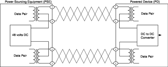
If you just ignore the POE 48 Volts in the image below, you can see Ethernet uses transformers on both sides.

This way there is no need for common ground as long as the common mode voltage stays below 1500V generally. The isolation specification of the transformers.

Imgur

And as a bonus you now also know how POE works. (802.3at)

However, CAT6A often has a shielded connector. The shield is then grounded to chassis using the little flaps inside the socket.

Source image

\$\endgroup\$
17
  • 4
    \$\begingroup\$ Your comment on CAT6A is incorrect. Shielding is not a property of the CAT specification. What you are referring to is FTP or STP. Additionally, you failed to the real answer is that differential signalling has better SNR than common ground signalling. \$\endgroup\$
    – Aron
    Commented May 4, 2017 at 9:53
  • 13
    \$\begingroup\$ @Aron No, the question specifically asks why Ethernet doesn't have a GND pin when other types of connection such as USB do. USB also uses differential signalling so that's NOT the "real answer". \$\endgroup\$
    – Finbarr
    Commented May 4, 2017 at 10:15
  • 2
    \$\begingroup\$ @Finbarr, USB is not fully differential. It uses specific voltages to indicate specific bus states. \$\endgroup\$
    – Jeroen3
    Commented May 4, 2017 at 10:45
  • 1
    \$\begingroup\$ @Jeroen3 I can see this in your answer already.. but I am not sure what do you mean by "common mode", and why 1500V should not be possible with ethernet, byt would be in USB or RS-232. \$\endgroup\$
    – mykhal
    Commented May 4, 2017 at 10:58
  • 1
    \$\begingroup\$ @mykhal in USB the 1500V don't matter, because things will break much sooner, because USB has a common ground \$\endgroup\$
    – Christian
    Commented May 4, 2017 at 11:11
36
\$\begingroup\$

Why is Ethernet not grounded? There are two reasons:

  1. It would create a ground loop between devices
  2. The device would also be more susceptible to ESD which is prevalent in cables that are being moved or handled (from triboelectric charging of the cable)

The reason Ethernet is more susceptible to a ground loop is because:

  1. The loops could be much larger than other cable specs, with 100m between devices. USB is 5m, RS232 us 15m. Ethernet devices are more likely to be in different rooms, whereas USB devices are usually grounded to a computer (or hub) and are on the same ground or in the same room on the same mains circuit.
  2. The voltage of ethernet is lower ±1V with ~10mA of current. RS232 is much higher at 5V or 15V. USB is 3.3V. This makes it more susceptible to error.

The companies and engineers that designed the ethernet spec had this in mind (there is a lot of thought that goes into specs)

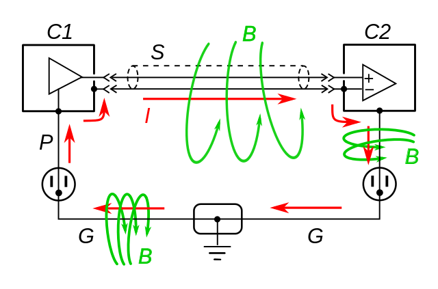
If you had a ground in between the transmitter and receiver it would create a ground loop. This ground loop would be formed by the cable and the return path would be mains ground as shown below. Any magnetic fields that flow through the loop would create a current along the cable (and the rest of the loop). Even if you isolated the signal wires this would be a problem because of mutual inductance between wires (wires run along side each other can couple currents from one to the other). This would inject noise (and cause potential bit error and packet loss).

enter image description here

So If you add an isolation transformer between devices, you break the loop and are still able to transmit a high speed signal between the transmitter and receiver. Another benefit of galvanic isolation, also increases the impedance of the cable to the device in the event of a large electrostatic discharge.

This is an example of isolation between two devices, ethernet has two isolation transformers, but the result is the same, it breaks the ground loop (and reduces common mode noise in conjunction with the twisted pair and common mode choke).

enter image description here

Images from wikipedia on ground loops

\$\endgroup\$
8
  • 2
    \$\begingroup\$ It's an example, of isolation between two devices. \$\endgroup\$
    – Voltage Spike
    Commented May 4, 2017 at 20:20
  • 2
    \$\begingroup\$ Why not use two isolation transformers instead? One in C1 and the other in C2, like in reality. It shouldn't be more difficult to understand than a single transformer. \$\endgroup\$
    – Oskar Skog
    Commented May 6, 2017 at 10:52
  • 3
    \$\begingroup\$ I'll probably modify this one when I get time... But whether you have 1 or 2 transformers it doesn't matter if you want to break the ground loop. The secondary purpose is to provide isolation for ESD, so it helps to have one on each end. To break a ground loop you only need one. I chose this diagram because it has AC mains in it, and others did not \$\endgroup\$
    – Voltage Spike
    Commented May 6, 2017 at 13:10
  • 1
    \$\begingroup\$ @mykhal The second scheme is sometimes used in audio applications where a ground loop has formed between two devices and the resulting current has components in the audio band. Adding an isolation transformer temporarily outside of the devices breaks the ground loop circuit. \$\endgroup\$ Commented May 6, 2017 at 13:10
  • 1
    \$\begingroup\$ ++ for making a decent fist of explaining the advantages of galvanic isolation - something which is often not appreciated or understood. \$\endgroup\$
    – danmcb
    Commented Jul 3, 2019 at 7:34
20
\$\begingroup\$
  1. Differential signaling means that there is no need for a common ground as a reference point. Also, negates the need for shielding, which is usually grounded.
  2. No DC power transfer again removes the need for a common ground and makes point #3 possible.
  3. Galvanic separation makes grounding counterproductive. Specs put considerable effort into making devices at different potentials able to work together so adding a ground wire would pretty much void this effort.

/edit: as Tom Carpenter pointed out, properly implemented POE, with isolated DC-DC converters, still retains the galvanic isolation and "no wire at ground potential" property. (Ok, POE breaks the galvanic separation part and adds kind of grounding, not clearly visible, yet it's there. But POE is a hack on top of the Ethernet, not an original part of the specs. Non-POE devices retain the original advantages.)

USB has differential signalling as well, but it also carries DC power. Mere existence of the powering possibility makes the common ground necessary.

RS-232 doesn't carry power, but the signal is not self-contained differential pair, it's a single wire referenced against the ground - that makes the common ground necessary.

\$\endgroup\$
7
  • 7
    \$\begingroup\$ Actually PoE should retain galvanic isolation. They do that using isolated DC-DC converters which provide the required 1500V isolation. \$\endgroup\$ Commented May 4, 2017 at 12:37
  • \$\begingroup\$ Also, the twisted pair property of the cable, will reject noise, as added noise in one loop, is subtracted in the next loop. So the shielding provided by a common grounded shield, is less important. Twisted pairing is a part of the cat spec. \$\endgroup\$
    – Henrik
    Commented May 4, 2017 at 12:52
  • \$\begingroup\$ @TomCarpenter Thanks, included. I've apparently dealt with crappy POE so far : ) \$\endgroup\$
    – Agent_L
    Commented May 4, 2017 at 12:54
  • \$\begingroup\$ @Henrik Rejecting noise is a property of differential signaling, twisting only enables it on crosstalk between pairs. Noise is never subtracted from the cable, it's only added to the opposite conductor. Then the differential mechanisms subtracts. Common shield wouldn't help reduce crosstalk anyway. \$\endgroup\$
    – Agent_L
    Commented May 4, 2017 at 13:03
  • 5
    \$\begingroup\$ @Agent_L probably, a lot of people just use the spare pairs on an Ethernet link to carry DC and call it PoE... \$\endgroup\$
    – Finbarr
    Commented May 4, 2017 at 13:04
18
+50
\$\begingroup\$

Grounding is often misunderstood to be the end-all solution for connecting things together. However, in most cases, even on short runs, grounding adds more issues than it solves.

The issue with sharing a ground over any distance is you are assuming both ends are at the same ground potential. In a perfect world that may be true, but in real life it almost never is.

Whether it be due to bad wiring, ground leakage, or EMI effects the ground over here on this monitor is different from the ground over there on your TV. As such, when you run a cable that includes ground between them, there will be a current running through that ground.

Moreover the common ground becomes the current return path for your signal. That means you are actually adding noise into the ground line. If your communication system uses multiple lines, they effectively share the same return path and the currents get far more complex, and the noise much worse, in the common ground.

enter image description here

The longer the cable the more voltage difference will be evident along that ground cable. If there is enough difference the delta between ground and the signal voltage will drop so low you are no longer able to distinguish the signal.

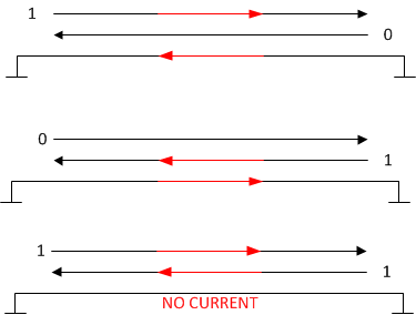
The image below demonstrates this. Note you have two lights above your ground in the distance. You can see that with a nice solid ground you can fairly easily tell in the middle two which light is turned on. However, in the right hand situation where the ground boundary is hard to identify, it is no longer possible to tell if that is a high or low light.

enter image description here

Standards like ETHERNET and other differential communication systems use a different technique that eliminates the need for a ground entirely.

By sending as a plus and minus signal over two dedicated wires the receiver can pick out the signal by examining the difference between those wires rather than comparing it to a passed reference voltage. (i.e. "Ground"). The image below indicates how this works. Notice even with the noisy signals on the right you can still tell which signal is being sent.

enter image description here

This technique not only allows the signal to be transmitted over much greater distance but also reduces the systems susceptibility to common mode noise. Since each signals current paths are also restricted to those two dedicated wires the inter-signal return path sharing is eliminated.

For Ethernet in particular, transformers are used to connect to the wires which provides complete isolation between the transmission medium and the sender/receiver.

\$\endgroup\$
6
\$\begingroup\$

To the mix of questions and comments of USB and Ethernet, such as why is Ethernet galvanically isolated, and USB is not:

Read up on USB history, and its mandates. It was to be a "low cost", "short distance" (5 meters) signaling port fit for computers at home and business, and low cost above all other needs. USB also had the mandate to improve data rate performance over parallel-printer and RS232 ports.

USB was to be put on all PC's manufactured. Whether the user needed it or not. That means it must be low cost. Parallel-printer ports and RS232 ports and the large associated connectors, had a serious cost penalty on all popular computers. And that made PC's and laptops, costlier, bigger, heavier and more power consumptive. USB, thus to be very "low cost", has no transformers to accomplish galvanic isolation. And it makes it easy to provide DC power to the peripheral. USB data signaling, for lack of a better phrase is "semi-differential". That is the current in the + and - lines of the cable, are about 95% numerically opposite matched (the + and -, are always slightly in error, of not being a perfect opposite current value), as a different transistor set drives each net, + and -.

Ethernet's mandate was and is; "reliable", "medium distance" communication, and low cost. But reliable and medium distance come first. Medium distance of 100 meters needs galvanic isolation very much. If two devices (such as a switch and a PC) were connected across two buildings with a few volts of ground potential difference, that's a rather bad thing, and unintended, unwanted, ground current will flow in that data cable. And that unwanted ground flow, can have all sorts of bad effects of harming the data quality and harming the equipment's, to possibly even endangering people.

Ethernet, also has different transistor sets driving each + and -, however the signal transformer shorts the + and - together, and thus the final + and - current flow is nearly a perfect, opposite match, down to nearly a single electron. Thus true differential signaling is achieved. True differential signaling allows the signal voltage levels to be further reduced, and the cable distances traveled, to be increased, and for unwanted EMI to be reduced.

Later came PoE for Ethernet. PoE's mandate was to bring "low cost" DC power to peripheral devices, ie, VoIP phones, Cameras, & Door-Access units. The PoE typically power exits the common Ethernet switch, to multiple devices, up to 100 meters in opposite directions. That PoE (48 to 57) VDC is a "star" connection to all the devices. That means the multiple power using devices "PD", share a common supply (this is NOT isolated power, per RJ45 connector at the PSE). Therefore it is a GUILT-Edged "shall" that the PD's shall maintain power isolation (as per the IEEE 802.3 standard), even on the PoE power inputs, by way of either an DC-to-DC isolated converter supply in the PD, or the PD is entirely in a non-conductive case, and never are its circuits ground plane connected to the local ground of the building or other nearby equipments (such as really low end cheap peripherals). Unfortunately, IEEE 802.3 at PoE standard does not spell this out very clearly.

Summary: Ethernet has transformers at both ends. If even a transformer failure happened, galvanic isolation from PD remote device, to the PSE in the Ethernet switch is not lost.

PoE, gives up DC power isolation, (for the sake of low cost) at the Ethernet switch, and leaves this isolation "shall" up to the PD peripheral manufacturer. Nobody is really checking on these manufactured items. If IEEE put a reward bounty on the violators, that would improve the situation.

The new PoE standard, IEEE is pondering for even higher voltages and currents, for more PoE power, should move toward some improved quality and safety. These should be on only commercial/industrial grade or better installations: 1) full power isolation at the PSE, for each connector. 2) required test reports for PSE & PD power isolation, that are filed, and downloadable for the public. To include the wiring diagram of the PI. 3) at the manufacturers cost, maintain a server, with a list of all PD's that meet the new standard. 4) consider making an industrial grade standard, if the cost of these improvements are too much for the low end consumer markets, yet still provide the serious level of standards, safety and traceability of industrial needs.

\$\endgroup\$
5
\$\begingroup\$

The answer thus far have missed one key element: shielding couples noise.

The Ethernet standard has included both UTP and STP (unshielded/shielded twisted pair) for decades.

IBM heavily influenced the original inclusion of STP, for its compatibility with Token Ring. The claim was that the STP shielding provides an extra layer of noise protection for the differential pairs (a bargain at only 5x the price!) However real-life experience quickly demonstrated that the shielding provided worse performance. Point sources of electrical noise were coupled to the shielding, where the noise then had the entire length of the cable to be coupled to the twisted pairs.

Shielding can also increase cross-talk. Pairs are twisted at slightly different rates -- a typical schedule is 11/12/13/14 twists per foot. This way they don't physically nest together to form a parasitic transformer when the cable is twisted and pulled during installation. This works great. Way better than you might expect. But the wiggling will stretch the shield between the pairs, coupling the signal to the shield and to the other pairs.

\$\endgroup\$
1
  • 1
    \$\begingroup\$ Well, the question was about ground wire, not shielding. Many cables have shield AND separate ground wire, eg USB. \$\endgroup\$
    – Agent_L
    Commented May 5, 2017 at 10:27
2
\$\begingroup\$

The Ethernet specification calls for devices to be galvanically isolated from each other - this post explains the isolation implications in more detail.

Since you mentioned power sources and grounding, the Wikipedia article on Power over Ethernet (PoE) may be relevant to you.

\$\endgroup\$
4
  • 2
    \$\begingroup\$ This doesn't really answer the question - it's just a pair of links. \$\endgroup\$
    – brhans
    Commented May 4, 2017 at 11:20
  • \$\begingroup\$ Please add the relevant parts of the referenced links to your post. Your answer will be useless when the referenced links get broken. Temporarily downvoted. \$\endgroup\$ Commented May 4, 2017 at 13:15
  • \$\begingroup\$ Also -1. Add some content from your two hyperlinks so that if they ever go dark, the post will still be relevant. \$\endgroup\$ Commented May 4, 2017 at 17:07
  • 2
    \$\begingroup\$ To be fair, the first link is to this very Stack, so unless that Q&A is deleted for some reason, that link will only be dark when this page is also. \$\endgroup\$ Commented May 6, 2017 at 13:11
2
\$\begingroup\$

One reason WHY TP ethernet, thank $DEITY!, is not using a common ground reference between stations has not been mentioned clearly enough:

An ethernet cable can run in excess of a hundred meters, probably even connecting two buildings.

The potential difference on even a well-executed grounding system, if measured at two points tens or hundreds of meters apart, is far from guaranteed to be even close to 0V - there can be DC or low frequency AC voltage due to current flow (due to leakage currents, actual fault currents, transients, or wiring mistakes/defects...) in the grounding system, and all kinds of interference.

AC potential differences will readily cause interference, while strong current flow across a grounded cable shield could actually turn into a fire hazard.

And all this assumes equipment being properly grounded in the first place, even worse things can happen if that is no longer the case.

Not worst, but bad case example what could happen with grounded (on both sides) shields : One PC has accidentally been connected with a two wire IEC cable (as has been found in the wild before!) on an RCD-less (old TN-C-to-the-socket ...) wiring system. This PC develops an internal short connecting live mains to the metal case, to which all the ground connections in that PC are connected. The other end of that connection is to a device where the grounding has been correctly implemented. The ethernet cable used is of the lightest build possible, with thin shielding material. And it is a 30 meter piece wound up in a coil since you were out of 5m cables. At that length, this shielding could have just the right resistance (around 15 ohms would be "perfect" on a 240V system) to pass a current that is small enough not to blow any fuses or automats, but well large enough to dissipate in excess of 1000 watts on the cable shield. Which will mean a lot of smoke and not unlikely an ignition hazard to stuff around it.

\$\endgroup\$
3
  • \$\begingroup\$ interesting experience but Ethernet TP can be grounded via 1000pF at both ends making that a HPF to AC line noise for shield or local earth ground connections ignored but a low impedance to shunt residual ethernet spectrum (EMI) from balance errors to pass the FCC levels. See my answer schematic, Worse yet is @Jeroen3 's answer that totally ignores the FCC requirement satisfied by RF CM ground connection and magnetics. \$\endgroup\$
    – D.A.S.
    Commented May 10, 2017 at 5:35
  • 1
    \$\begingroup\$ Scenario is theoretical, but possible - and catastrophic. There is a good reason the standards on ground resistance in actual grounding systems are so darned strict - a defective grounding in any scenario where there could ever be mains voltage can make hazards worse than no grounding. \$\endgroup\$ Commented Jun 8, 2017 at 0:12
  • \$\begingroup\$ true but irrelevant as the CM load R is 1000pF coupled to local ground is necessary whether floating or earth grounded. ( to local standards)min order to provide high 2 way CMRR of noise. \$\endgroup\$
    – D.A.S.
    Commented Jun 8, 2017 at 0:33
1
\$\begingroup\$

Both RS-232 and USB have signals referenced to ground, that's why you need one. (Yes, D+ and D- signals in USB are used independently from each other with GND as a reference during device discovery). Ethernet signals are purely differential, so no GND reference is needed.

\$\endgroup\$
1
\$\begingroup\$

What makes you think it has no ground connection?

  • "Ground" by definition is a 0V reference for some local circuit.
  • Earth ground is one connected to the outside terraferma.

As you may know, all laptop/tablets have floating ground unless connected to some port with an external earth ground such as a VGA cable to a 3 pronged LCD monitor due to the galvanic transformer isolation in the battery charger.

Ethernet also has no signals in the lower spectrum including DC because of the Bi-Phase encoding methods.

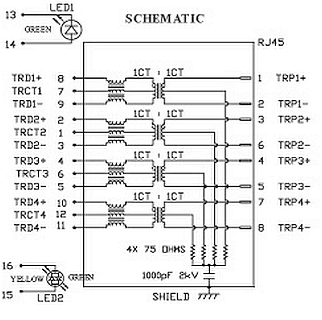
More important is that for signal integrity and EMI reduction for egress and ingress, the signals are transmission lines with 75 Ω termination and balanced with CM transformer and 1:1 centre tapped transformer. This raises the CM impedance on the user side for isolation while maintaining the differential impedance on the cable side to local ground in the upper spectrum where signals exist.

See the "ground connections" below

  • via 1000pF coupling cap and 75 Ohm terminators enter image description here
\$\endgroup\$
5
  • \$\begingroup\$ CLEARLY , anyone that there is an AC ground for the Ethernet diff signals and without this it would fail as the CM noise levels of floating CM noise would be excessive even with CM choke with 100MHz~1GHz BW. Since the Terminators are AC grounded an earth ground is not needed, but there is a CM ground connection between connectors. So much for weak arguments of ground loops. These are not AC line loads currents! Why did everyone not understand this? (in the high scored answers). @laptop2d pls advise \$\endgroup\$
    – D.A.S.
    Commented May 8, 2017 at 6:14
  • \$\begingroup\$ ALthough OP asked about DC ground wire not included. It is not necessary since the current is shunted to AC ground via cap and thus the signals are in fact ground referenced at each end by definition Gnd = local 0V reference with low impedance to DC supply and AC ethernet common mode noise currents being shunted to local gnd to reduce EMI. and there is no need for AC line or DC shunting of noise as there is no signal here in lower spectrum. THis is critical to understand and not shown in any other answers. \$\endgroup\$
    – D.A.S.
    Commented May 8, 2017 at 18:50
  • 1
    \$\begingroup\$ I fail to understand the ignorance of a person who (-1) but cannot articulate why \$\endgroup\$
    – D.A.S.
    Commented Jun 10, 2017 at 1:55
  • 1
    \$\begingroup\$ I think you got a -1 because even with some basic electronics knowledge I had difficulty understanding your text. I would have LIKED to understand what it all means, because it looks like an interesting answer, but there seems to be some advanced EE concepts in there which is better suited for EE geeks and not for beginners or hobbyists. \$\endgroup\$
    – Casper
    Commented Jan 18, 2018 at 2:38
  • \$\begingroup\$ The ground connection is clear on the schematic. Thats the answer. The reasons use common words for EMI.used by EE's in this field. \$\endgroup\$
    – D.A.S.
    Commented Jan 18, 2018 at 3:01

Your Answer

By clicking “Post Your Answer”, you agree to our terms of service and acknowledge you have read our privacy policy.

Not the answer you're looking for? Browse other questions tagged or ask your own question.