1
\$\begingroup\$

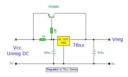
I'm looking to draw about 6A. I have an LM338 regulator that can supply up to 5A. Searching the internet I came across this schematic,

enter image description here

So basically when the 1R resistor drops 0.6V then the transistor conducts the remainder of the current. I calculated my own values for those two resistors. Was wondering if my values are fine so that I can purchase the resistors

I want 3A to pass through the regulator, so I got R1 to be,

R1 = 0.6V / 3A = 0.2 ohm

PR1 = 3^2 * 0.2 = 1.8 W

The remaining 3A can pass through the transistor, using the 2N6491 PNP transistor, this one

Transistor

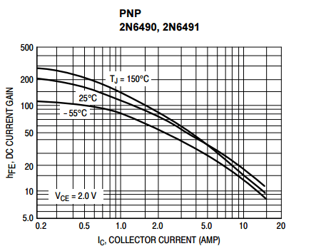
From the datasheet hfe at 3A is 50

enter image description here

So, Ib = Ic/hfe = 3A / 50 = 0.06 A

Vb = Vin - 0.6 (Vin = input voltage to the regulator)

= 13.85 - 0.6 = 13.25 V (Base voltage)

Rb = Vb/Ib = 13.25 / 0.06 = 221 ohm (Base resistor)

\$\endgroup\$
4
  • \$\begingroup\$ Did you look into switching power supplies? Do you have an appropriate heatsink? \$\endgroup\$
    – Christian
    Commented May 4, 2017 at 8:36
  • \$\begingroup\$ 3/0.6 = 5; your R should be 1/5th the schematic. look up "series pass transistor" for tons more info. make sure to get wire-wound or several 1W resistors. \$\endgroup\$
    – dandavis
    Commented May 4, 2017 at 9:00
  • \$\begingroup\$ LDO's are horribly inefficient and require big heat sinks. Since you neglected Pd and Vin-Vout range, I urge you to add a few more parts like a comparator , 10A 10uH choke and a 10~20mOhm MOSFET , you have a Buck regulator with <<10 % losses, rather than massive losses. \$\endgroup\$
    – D.A.S.
    Commented May 4, 2017 at 19:18
  • \$\begingroup\$ Possible duplicate of Voltage regulator Current regulation \$\endgroup\$ Commented May 23, 2018 at 12:27

4 Answers 4

2
\$\begingroup\$

I get the following equation for computing \$R_1\$:

$$R_1=\frac{V_T\cdot \operatorname{ln}\left(\frac{I_C}{I_{SAT}}\right)+ \frac{I_C\cdot R_2}{\beta}}{I_L - I_C}$$

Which, given: \$V_T=26\:\textrm{mV}\$ (room temp), a model value I found of \$I_{SAT}=65\:\textrm{fA}\$, your \$\beta=50\$, \$I_C=3\:\textrm{A}\$, \$R_2=10\:\Omega\$, and \$I_L=6\:\textrm{A}\$, I get \$R_1\approx 473\:\textrm{m}\Omega\$. The nearest standard value would be \$470\:\textrm{m}\Omega\$, which leads to:

$$I_L=\frac{\beta\cdot V_T}{\beta\cdot R_1 + R_2}\cdot\operatorname{LambertW}\left(\frac{I_{SAT}}{\left(\frac{\beta\cdot V_T}{\beta\cdot R_1 + R_2}\right)}\cdot e^{I_L\cdot\frac{R_1}{V_T}}\right)\approx 2.988\:\textrm{A}$$

(If you are interested in what the LambertW function is [how it is defined] and in seeing a fully worked example on how to apply it to solving problems like these, then see: Differential and Multistage Amplifiers(BJT).)

Which may be close enough.

I'm sure you can work out the power dissipations for the components from here.

Just to make this more complete, using the above values and \$R_1=470\:\textrm{m}\Omega\$, I get the collector current for the bypass BJT to be:

$$\begin{array}{l|c|c|c} _\beta\quad ^{I_{SAT}:} & 30\times 10^{-15}\:\textrm{A} & 65\times 10^{-15}\:\textrm{A} & 100\times 10^{-15}\:\textrm{A}\\\hline 40 & 2.76\:\textrm{A} & 2.78\:\textrm{A} & 2.80\:\textrm{A}\\50 & 2.96\:\textrm{A} & 2.99\:\textrm{A} & 3.00\:\textrm{A}\\60 & 3.11\:\textrm{A} & 3.14\:\textrm{A} & 3.16\:\textrm{A} & \\ 80 & 3.33\:\textrm{A} & 3.36\:\textrm{A} & 3.38\:\textrm{A} \end{array}$$

As you can see, substantial \$\beta\$ variations probably have the largest effect on the current sharing. Probably not a surprising result. But variations on \$V_{BE}\$ due to the saturation current variations, \$I_{SAT}\$ are of much less importance (when room temperature is held constant.)


None of the above deals with temperature variations as the BJT heats up under load. You'll need to examine the equations with variations in \$V_T\$. I expect the temperature issue to be an important consideration. So you may want to figure out the expected temperature rise in your BJT, based upon the value for \$I_L\$, the \$V_{CE}\$ drop and the base current and the \$V_{BE}\$ drop, together with the thermal resistance you expect, to work out that temperature. Once you have that estimate, plug that into the above equations and see what you get. Keep in mind that both \$V_T\$ and also \$I_{SAT}\$ are functions of temperature and that the latter one dominates and overwhelms the other, so that you can expect a shift in the \$V_{BE}\$ of about \$-2\:\frac{\textrm{mV}}{^\circ C}\$ to \$-2.4\:\frac{\textrm{mV}}{^\circ C}\$.

It was interesting enough for me to check on the thermal details. So worked out the saturation current differences (it goes by a power of 3.) A \$45\:^\circ\textrm{C}\$ rise over ambient would shift \$V_T\$ to about \$29.6\:\textrm{mV}\$ but it would also shift \$I_{SAT}\$ from \$65\:\textrm{fA}\$ to about \$150\:\textrm{fA}\$. Hence, the collector current in the bypass BJT goes from about \$3\:\textrm{A}\$ to about \$2.9\:\textrm{A}\$, instead. That provides a rough idea what to expect with temperature changes, I think.

\$\endgroup\$
2
\$\begingroup\$

The change you're considering looks like it doubles the number of parts in your circuit. Those new parts will be getting hot too, so bodging them onto your board isn't really possible for long-term reliability, they could do with decent heatsinks.

Unless you really do have to keep your 78xx regulator, I'd strongly recommend you change your design to a higher-current linear regulator or preferably a switching regulator.

That way, you'll have a single output stage rather than the half-transistor half-regulator circuit you were looking at. And that single output stage will have all the protection benefits of your chosen regulator: short-circuit, under/over-voltage, over-temperature etc.

If you want to really simplify things but spend more, you could use a DC-DC 'brick': a pre-assembled module with heatsink.

\$\endgroup\$
1
\$\begingroup\$

That's a typical circuit as you can find in a datasheet. The key is to pick the resistor to set the max current through the regulator.

The adjustor can be a p ch mosfet as well - more robust vs. 2bday breakdown. But less efficient.

If you can tolerate some fluctuation in output voltage, a npn or a n-ch midget can be used here as well. Cheaper, better at handling large current and power dissipation. Not as well known or as widely used.

\$\endgroup\$
1
\$\begingroup\$

With that kind of current, you should seriously think of ditching the linear regulator altogether and use a buck switcher.

The 7805 needs at least 2.5 V headroom, and the extra transistor adds some more. In the end the input voltage will be at least a bit over 3 V higher than the output. That times your 6 A current means a minimum of about 20 W will be dissipated as heat at full load. Yikes! And that's with the input voltage trimmed to the bare minimum. Since that is unregulated, its average will inevitably be higher than that.

A buck switcher will be cheaper and smaller than whatever it will take to get rid of 10s of Watts of heat.

\$\endgroup\$

Your Answer

By clicking “Post Your Answer”, you agree to our terms of service and acknowledge you have read our privacy policy.

Not the answer you're looking for? Browse other questions tagged or ask your own question.