0
\$\begingroup\$

Hi StackExchange community,

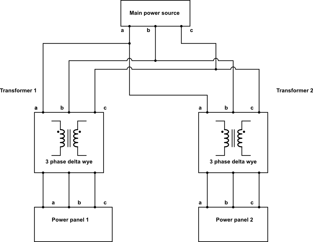
Here I have a wiring diagram that represents a portion of a circuit found in a hospital.

The voltage difference was measured between phase A on the left and the phase A on the right and the voltage difference was found to be 120 V. The voltage difference between phase A on the left and phase A on the right should be 0 V.

Can anyone suggest possible reasons for this malfunction? A theory of mine was that the connections between phases may have been flipped somewhere along the way but I would appreciate some input.

Thank you.

enter image description here

\$\endgroup\$
0

1 Answer 1

1
\$\begingroup\$

I don't see any "phase A" I see lots or a's b's and c's.

However, I am guessing you mean at the panels.

Since in your diagram, they appear to be isolated what you are reading may be a meter effect.

However it is far more likely there is a common neutral / ground connected in there somewhere you are not showing us, in which case the transformers may not be connected the same way.

\$\endgroup\$
2
  • \$\begingroup\$ Thanks. I have very limited info right now as I have not been to the site where this problem appeared. It's very possible there is a common neutral/ground between the two sides but how could this cause this type of malfunction? \$\endgroup\$
    – user8357
    Commented May 15, 2017 at 19:51
  • \$\begingroup\$ Wiring up three phase transformers is often pretty much at the discretion of the electrician. Same guy will usually do them the same way... but there is no guarantee of either. \$\endgroup\$
    – Trevor_G
    Commented May 15, 2017 at 19:58

Your Answer

By clicking “Post Your Answer”, you agree to our terms of service and acknowledge you have read our privacy policy.

Not the answer you're looking for? Browse other questions tagged or ask your own question.