First, let me say thanks for taking the time to read/help. I'm fairly new to electronics design, although I have a decent working knowledge (and am not afraid to do the legwork to figure out how something works through my own legwork). Any help would be greatly appreciated. I'm not afraid to go do the legwork to suss out a solution, but I need the help of someone seasoned, as even the most basic suggestions will cut down the time dramatically. Again, thanks for taking the time!
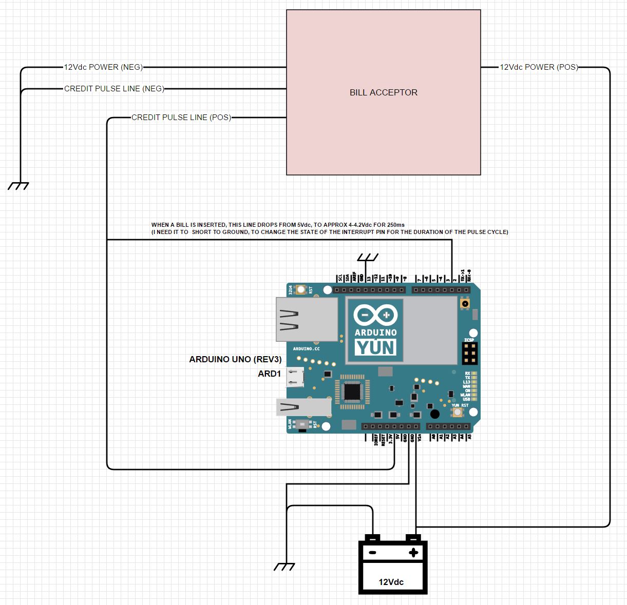
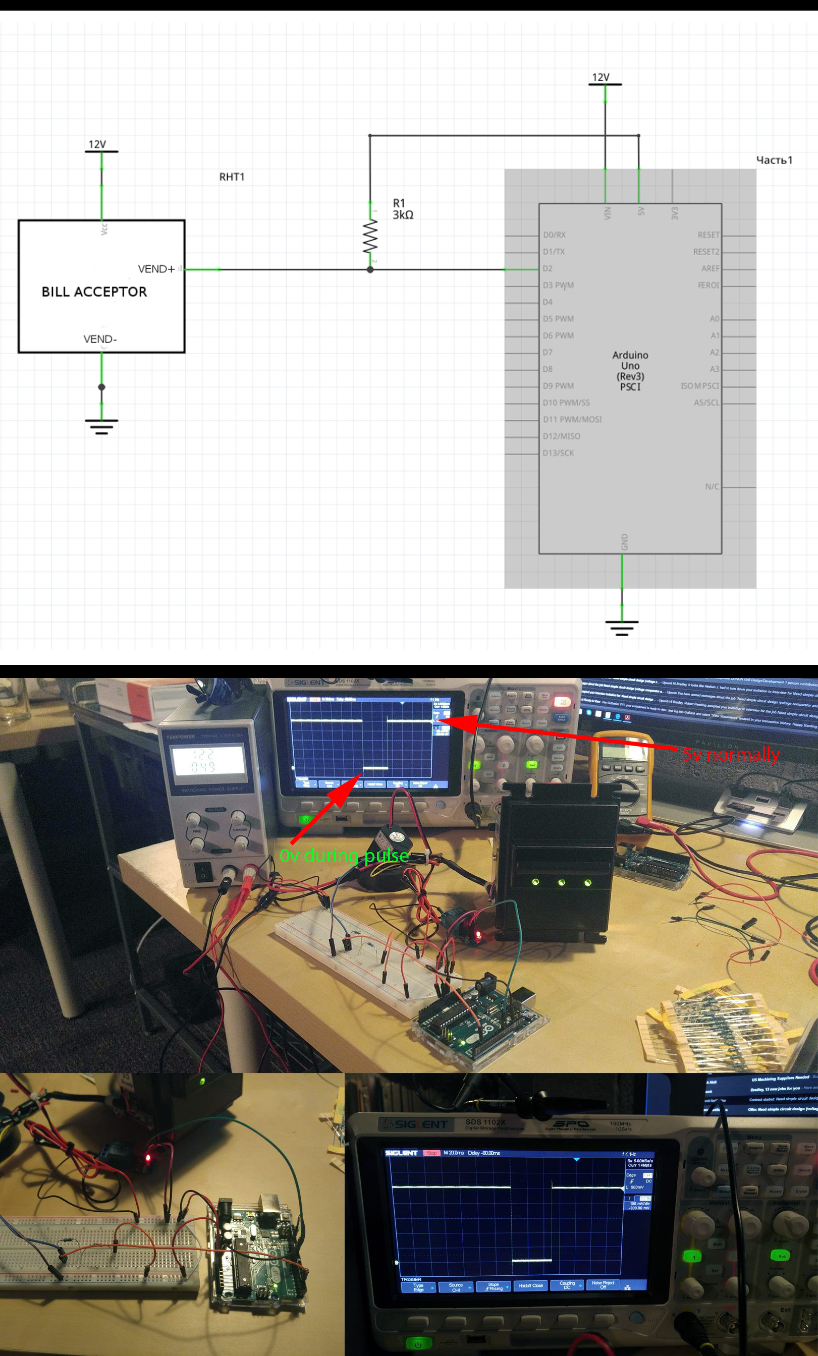
Basically, I have a bill acceptor (takes a variety of monetary notes for payment). This Bill acceptor is designed to output a "pulse" when a bill is inserted/accepted. I have the circuit hooked up as the image below, and it's working properly. I've seen the output pulse on my oscilloscope, when reading between the Credit Pulse(Pos) and Common Ground.
When a bill is inserted, the 5Vdc line pulses on the scope for 250ms. It falls from 5Vdc to around 4-4.2Vdc. What I NEED is to cause this line (at the interrupt pin on the Arduino) to read 0Vdc, as the small change in voltage isn't triggering a HIGH/LOW state change at the pin (the Arduino doesn't recognize the pin as being LOW during the pulse cycle).
Any suggestions you have, or direction you might point me in would be very helpful. I apologize for the rudimentary nature of my schematic, or any faux pas I might have tripped over here. I've tried to be as detailed as possible. Thanks again for your time and assistance!
NOTE: I'm actually using an Arduino Uno Rev3 (I didn't have a schematic symbol for it, but found one that would suffice).


