0
\$\begingroup\$

I am trying to interface a bill acceptor which provides RS232 (TTL level) with the Arduino's UART.

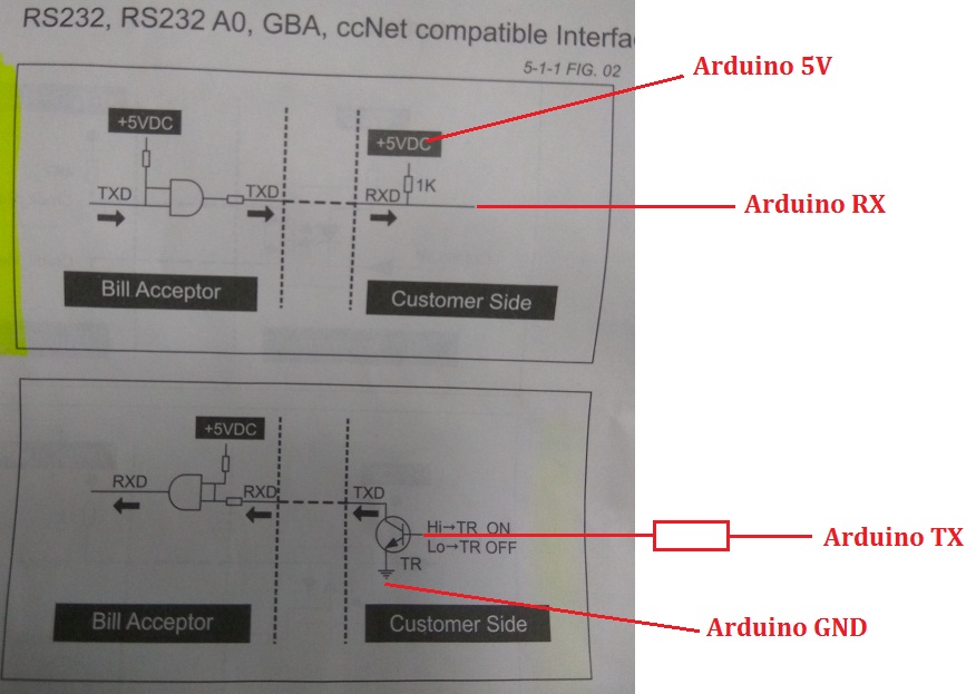
The manual of the bill acceptor provides the I/O circuit below.

I have tried two ways to no avail.

In the first way, I make the connection with the 2 x 1K resistor and 2n2222 transistor with a breadboard like this:

enter image description here

The RS232 interface of the device has 4 wires: TX, RX, Download VCC (which I connect to Arduino's 5V - I also tried not connecting it, still a bit confused about this wire) and GND (which I connect to common GND with Arduino).

I also tried the following to no avail: enter image description here
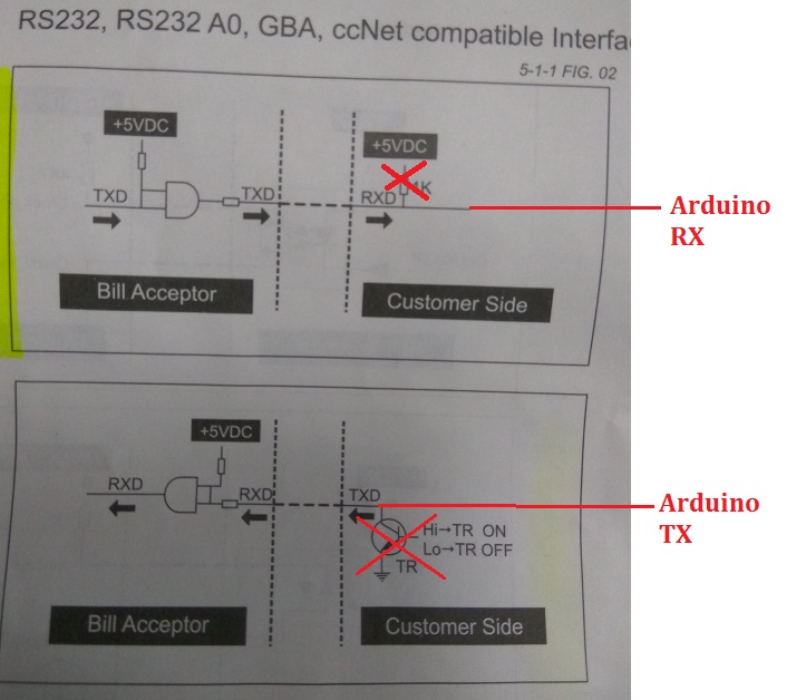
Upon starting up, even from the beginning when not connected with the Arduino, the device flashes in a way that it means its RS232 is not working (by checking with the trouble shooting part of the manual)

Connecting like above also gives the same result.

It's a bit weird to me that the guy who sold me this acceptor, after asking me to try so many ways (checking wires, re-check DIP switches etc.) finally told me that the RS232 interface of the acceptor has to be connected in order for it to work, which is kind of weird to me. I made the above attempts following his claim.

Could anyone tell me where I went wrong? Or is it a defective unit?

Many thanks! Dave

\$\endgroup\$
0

1 Answer 1

5
\$\begingroup\$

The first thing to do is to verify the polarity level of the signals. The pullups imply the idle level is high, which is normal for logic-level RS-232. However, the transistor in the first diagram inverts the signal, which implies the opposite. See what state the transmit lines are in when nothing is being sent.

Also verify that the you are really using logic-level RS-232 on the microcontroller end. If there is a RS-232 converter chip in there, it won't work right. You want to connect the microcontroller UART lines to the bill acceptor UART lines directly, assuming the micro follows the usual convention of idle is logic high.

Also, test each direction independently. Do something with the device that should cause it to send something, and watch its TX line on a scope. That will tell you polarity, baud rate, and the like. Then send it some bytes that should cause something visible to happen to test the other direction.

\$\endgroup\$
4
  • \$\begingroup\$ @ Olin Lathrop: yes, its RS232 logic level, I am connecting the device with Arduino Mega, which provides only UART. I have measured the bill acceptor side (against its GND) upon starting up (and blinking "Disable") without connecting anything on the Customer side: + Download VCC: +5V + TX: +5V + RX: +4.88V \$\endgroup\$
    – Dave
    Commented Aug 5, 2016 at 2:18
  • \$\begingroup\$ Now I am suspecting that the unit should be sending some "hello" message upon start up and awaiting some kind of answer before it's Enabled. \$\endgroup\$
    – Dave
    Commented Aug 5, 2016 at 2:19
  • \$\begingroup\$ I confirm that the first diagram works, at least for the RX of customer side. Device uses even parity that I didn't know. Already receive the start-up character of the device. Just don't know why can't send via customer side's TX. For the transistor, I am using a 2N2222 with a 1K resistor connected to the customer side's TX... \$\endgroup\$
    – Dave
    Commented Aug 5, 2016 at 6:32
  • \$\begingroup\$ @Dave: if RX in the first diagram works, then the device and microcontroller are both probably using logic level signals with idle high. You should still check this on the scope, though. If the above is true, then using a transistor is guaranteed to not work, since that inverts the signal. \$\endgroup\$ Commented Aug 7, 2016 at 0:47

Your Answer

By clicking “Post Your Answer”, you agree to our terms of service and acknowledge you have read our privacy policy.

Not the answer you're looking for? Browse other questions tagged or ask your own question.