7
\$\begingroup\$

I am trying to implement the Hodgkin-Huxley model for simulating neurons using LTSpice. One feature of this model is that the resistances at any given time actually depend on the transmembrane voltage at that time. Is there a way, in LTSpice, to change the values of resistors dynamically in a simulation?

I can find answers on how to vary the value of a resistor in pre-defined increments during a simulation. However, this approach will not work in this case, because I don't know these increments before the simulation starts. Rather, they must be recalculated dynamically from a particular voltage. Does LTSpice (or any other version of Spice, for that matter) have this capability?

EDIT: To be more specific about what the Hodgkin-Huxley model entails, the simulation code I need basically boils down to this schematic, where the g's represent the conductances, the E's are all constant voltages, gL is constant, and the other conductances all update according to these equations:
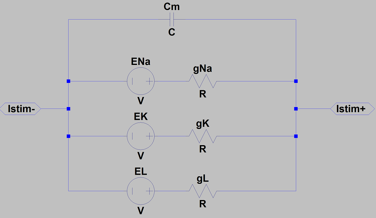
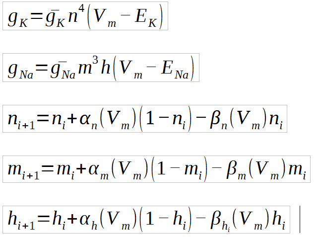
where m, n, and h are state variables, and Vm is the transmembrane voltage (the voltage between Istim+ and Istim- in the above schematic). The alpha's and beta's are known functions of the transmembrane voltage.

In particular, I need to be able to keep track of the "current values" of the m, n, and h parameters during the simulation because the next value of these variables will depend on them.

\$\endgroup\$
3
  • \$\begingroup\$ Can you give a more explicit example of what you want? Sounds like you want to set resistance to a variable {X}, and have {X} to be a function of another value, say the voltage at node 012 or something? I've been wondering if that is possible, but I don't know how as of yet. \$\endgroup\$
    – Bort
    Commented Jun 27, 2017 at 17:13
  • \$\begingroup\$ Let's say you can vary resistance with a voltage. What do you do with that variable resistor i.e. what signal or voltage does that control. I ask because there may be a way of doing this that's a little off centre. \$\endgroup\$
    – Andy aka
    Commented Jun 27, 2017 at 18:58
  • \$\begingroup\$ I've edited the OP to give the specifics of the model I want to simulate. \$\endgroup\$ Commented Jun 29, 2017 at 23:26

2 Answers 2

9
\$\begingroup\$

I haven't spent much time considering a method for this. But it sounds as though you may have an arbitrary function that computes \$R\$ based upon an applied voltage \$V\$.


You might use LTSpice's .FUNC to do something like this:

.FUNC MYFUNC(A) {3*A}

(That's just a random function to illustrate the idea.)

Then you could just drop down a resistor, which will default to a value of "R". Now, right-click on the "R" there and get a prompt to allow you to change it. The dialog box should be titled "Enter a new value for Rx". Enter "R={MYFUNC(V(N005,N006))}" or something like that (if you know the node names, use those.) That should allow you to make up an arbitrary function based upon some formula you concoct.

You don't have to use .FUNC, by the way. You can just enter the formula directly into the "R={...}" expression there.


However, the above method has at least one problem. The node names will have to be hard-coded. So this can be a problem as you move forward in a circuit and want the "resistor" to have its value depend solely on a complex function of the impressed voltage on it, regardless of the global circuit node names. For that, I'd go with a .SUBCKT approach.

Here, you'd just drop down an new R like you always do. Then ctrl-right-click the R symbol. Edit the "Prefix" to "X", modify "InstName" to specify "X1" or "X2" or something like that, get rid of the "Value" entry (edit it and delete it), and modify the "SpiceLine" entry to specify a subcircuit name of your choice. Now you have a nice subcircuit symbol that looks like a resistor, but LTSpice now thinks it is a subcircuit.

Now just add a subcircuit. Hit "S" and get the Spice directive dialog box to pop up. Now enter something like this (I'm using the subcircuit name of "XYZ" here):

.SUBCKT XYZ 1 2
GRES 1 2 VALUE={1.0/(10k*V(1,2))}
.ENDS

What I've done above is just use a "G" device. This device can now look at its own terminals, get the voltage from them, and then compute some current based on that. In the above formula, I decided I wanted to mimic a resistor whose resistance magnitude is, ignoring dimensional analysis for now, \$R=V^2\cdot 10\:\textrm{k}\Omega\$. (I squared the voltage to make sure the result is always positive or zero. Allowing zero probably isn't the greatest idea. So just be aware.) Given that, you can work out that the current should be \$\frac{V}{V^2\cdot 10\:\textrm{k}\Omega}=\frac{1}{V\cdot 10\:\textrm{k}\Omega}\$. So that's how I got the equation to use there.


You can do combinations. You can create separate .FUNC functions and use those inside of your subcircuit. You can make the subcircuit as complicated as you want, too.

\$\endgroup\$
5
  • \$\begingroup\$ Your point about making sure the value is always positive or zero is excellent and deserves great emphasis! It is very easy to get into solver stability issues with behavioral sources if you're not careful. \$\endgroup\$
    – compumike
    Commented Jun 27, 2017 at 20:19
  • \$\begingroup\$ You can name nodes with the f4 key, I'm sure you know this but it wasn't written in your post \$\endgroup\$
    – Voltage Spike
    Commented Jun 27, 2017 at 20:54
  • \$\begingroup\$ @laptop2d I know. I thought about adding a discussion on that point, as well. But I realized that it is a LOT BETTER to just use an "X" subcircuit, instead. Now you have access to its own terminals, no matter how they are placed on a schematic. So I squandered my time on that, instead. \$\endgroup\$
    – jonk
    Commented Jun 27, 2017 at 22:18
  • \$\begingroup\$ @jonk This looks like it might be almost exactly what I need, thanks. I've edited the OP to list the schematic and equations I need to implement in the simulation, but to summarize, the only thing missing from this answer is that I need to store the values of some state variables at any given time in the simulation (namely n, m, and h). Would creating some disconnected resistors, and storing the state variables in the resistances, do the job? \$\endgroup\$ Commented Jun 29, 2017 at 23:33
  • 1
    \$\begingroup\$ @IanMathWiz I don't want to do your work for you, as you know it a lot better than I do. Besides, I don't feel like working on generating functions to solve recurrences right now. But I can say that state variables are traditionally captured in Spice as either capacitor (voltage) or inductor (current) energy. \$\endgroup\$
    – jonk
    Commented Jun 30, 2017 at 0:36
1
\$\begingroup\$

Use Behavioral Sources and Expressions to define a behavioral voltage source where the voltage is proportional to the current, but the "constant of proportionality" varies with other voltages.

Ohm's Law goes from the simple form:

$$V_x = I_x \cdot R_x$$

to a form where we let the resistance be a function of other voltages or currents in the circuit:

$$V_x = I_x \cdot f(v_a,v_b,i_j,i_k,\dots)$$

Here's a quick example:

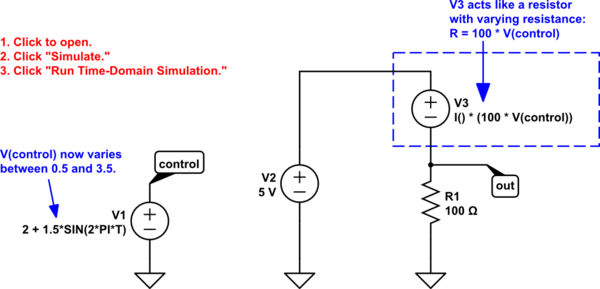
schematic

simulate this circuit – Schematic created using CircuitLab

Open the circuit in CircuitLab to simulate. In this example we've defined V3 to be a behavioral voltage source with the expression:

$$V_{\text{V3}} = I_{\text{V3}} \cdot 100 \ V(\text{control})$$

Since the element-wise voltage is proportional to the same element's current, it looks like a resistor, with effective resistance:

$$R_{\text{eff}} = 100 \ V(\text{control})$$

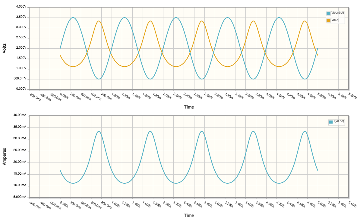
If you run this simulation, you'll get the expected current and voltage plots for the time-varying resistive voltage divider: behavioral sources simulate varying resistance in CircuitLab

\$\endgroup\$

Your Answer

By clicking “Post Your Answer”, you agree to our terms of service and acknowledge you have read our privacy policy.

Not the answer you're looking for? Browse other questions tagged or ask your own question.