0
\$\begingroup\$

a busy cat

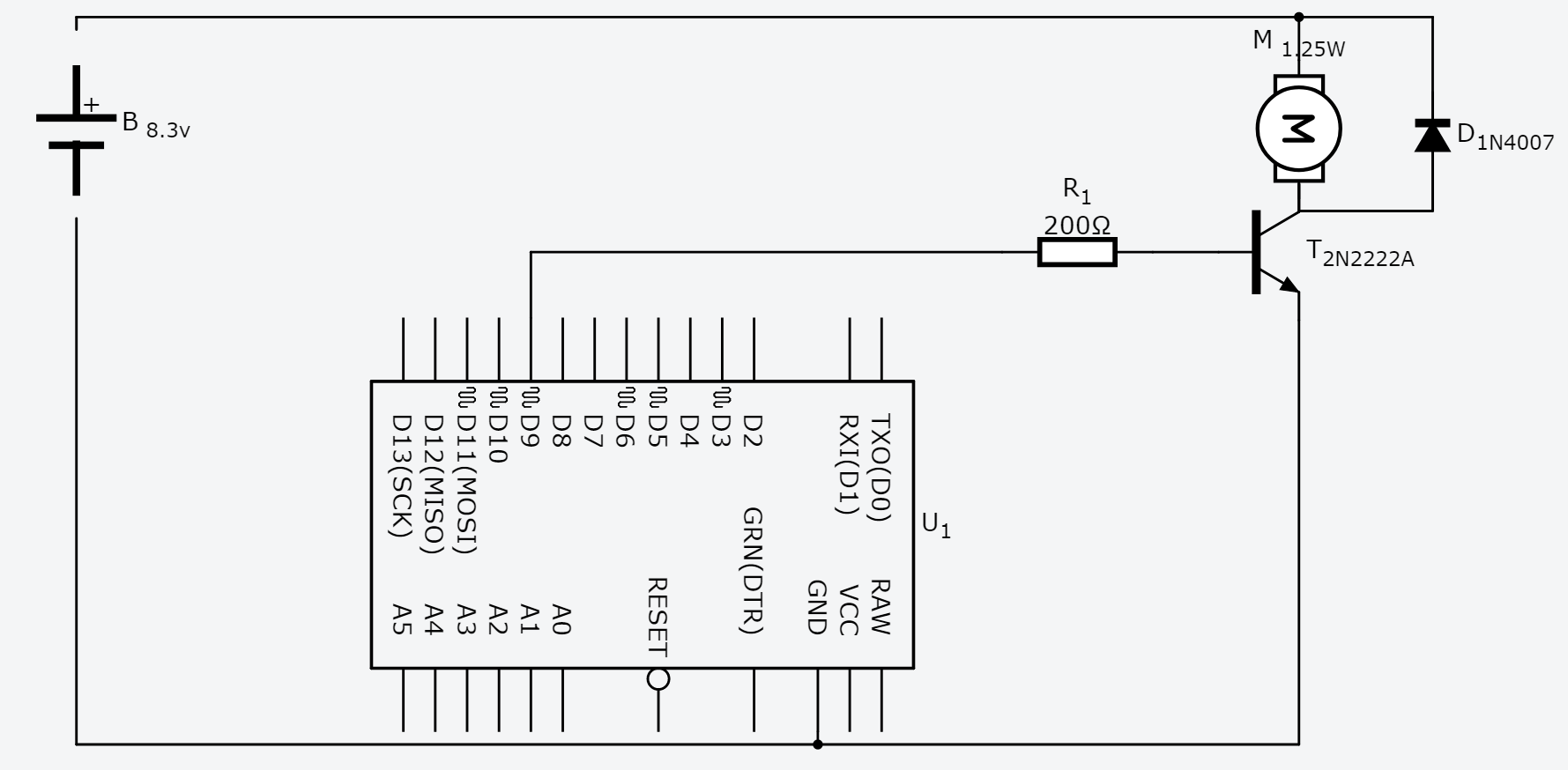
Hi there, I've created the circuit following this thread. The arduino D9 pin get 5v and I measured with the tester a VBE of 0,82v, which is right for the transistor saturation. Unfortunately the pump doesn't start! I've tried attaching the pump directly to the 8.3v battery pack (2x18650 batteries in series) and works fine, consuming 150mA. To calculate the 200ohm resistance for the driving current of the base I've followed this guide. The arduino port when HIGH provides 4.7v, so 4.7-0.80=3.9v drop. The resistance should be 3.9V/0.02A=195ohm, i've just rounded to 200.

The pump is connected with the + to the + of the battery.

Any suggestions on how to make it working?

\$\endgroup\$
12
  • 1
    \$\begingroup\$ Have you measured how much is the voltage at the - side of the motor? How much current flows through the motor? \$\endgroup\$
    – nickagian
    Commented Jul 4, 2017 at 8:49
  • 1
    \$\begingroup\$ pumps need a lot extra to start (think slow-blow fusing), more than what a dmm will later show when measuring current. you're right on the margin of a fully-running pump. \$\endgroup\$
    – dandavis
    Commented Jul 4, 2017 at 8:56
  • 1
    \$\begingroup\$ If you read a bit further on the page you linked to you'll find that user SPhoenix had success using a TIP142 transistor. If you're going to be doing a bit of this sort of thing, you might as well get a pack of five-or-so of those transistors in TO-220 cases and perhaps a couple of suitable heatsinks. \$\endgroup\$ Commented Jul 4, 2017 at 9:51
  • 1
    \$\begingroup\$ The 2N2222 supports 800mA, but I suspect it cannot support the start-up current required by the motor. \$\endgroup\$ Commented Jul 4, 2017 at 12:59
  • 1
    \$\begingroup\$ Replace the transistor with a new one and replace the motor with a resistor and LED. Get that working and then try with the motor. You can also measure the motor current with your meter by connecting them in series directly across the supply voltage. When you have that you can check the transistor datasheet to see if it can handle it. \$\endgroup\$
    – Transistor
    Commented Jul 4, 2017 at 14:43

2 Answers 2

0
\$\begingroup\$

I propose that you temporarily disconnect the node to MCU pin D9, and first manually tie it to the 5V supply, and see if the motor runs. This will eliminate any software bugs and verify the power circuit.

\$\endgroup\$
3
  • \$\begingroup\$ Ok, I'm going to connect VCC (the arduino is connected via usb) to the resistance at the base of the FET. I'm quite sure there are no software bugs since the code is quite trivial and i can check that the voltage flips between 0v and 5v on D9 with the tester. I'm just not sure if the resistance is "right" to drive the correct amount of current \$\endgroup\$
    – Malo87
    Commented Jul 4, 2017 at 14:35
  • \$\begingroup\$ FET? What FET? I can't see one anywhere. \$\endgroup\$
    – Finbarr
    Commented Jul 4, 2017 at 15:01
  • \$\begingroup\$ I beg your pardon. A user asked waht FET i was using, and I've used the same erroneous term. \$\endgroup\$
    – Malo87
    Commented Jul 4, 2017 at 20:55
0
\$\begingroup\$

Ok, I've found the problem! - I've blown up the fuse of my tester for the 600mA port. Please note that the pump is using 150mA, so it must have been some short circuit.

  • I've notice that because replacing the pump with a resistance and a LED was indeed working, while I was hooking up the terminals of the pump trough the multimeter

Thanks for the help, I'm going to ask a separated question on how to connect the battery chargers in the circuit

\$\endgroup\$
4
  • \$\begingroup\$ You must not connect a charger for a lithium cell to this circuit. You'll have to remove the cells and put them individually into the charger. \$\endgroup\$ Commented Jul 4, 2017 at 22:18
  • \$\begingroup\$ Mhmh.. Why not? this should work fine since the +/- terminal are protected.. \$\endgroup\$
    – Malo87
    Commented Jul 4, 2017 at 22:48
  • \$\begingroup\$ Two glaring reasons: one, a lithium charger that is itself remotely safe will be monumentally confused by having an unexpected load on the cell it is charging, and two because your circuit requires two cells in series, while that is a charger for a single cell in isolation. Best to leave lithium batteries to those who understand them. \$\endgroup\$ Commented Jul 5, 2017 at 0:23
  • \$\begingroup\$ Ok, I got your point.. I'm no expert. Nevertheless, i've got two TP4056 modules, one for each battery. I'll research a bit more on how to use them for both load control and charging. I'm using [this] (blog.zakkemble.co.uk/…) as a starting point. \$\endgroup\$
    – Malo87
    Commented Jul 5, 2017 at 11:52

Not the answer you're looking for? Browse other questions tagged or ask your own question.