7
\$\begingroup\$

To give some context, I am trying to emulate controller input to the N64 via a GPIO pin on the Raspberry PI.

In an attempt to accomplish this, I have one of the PI's GPIO's in a pull-up configuration connected to the data line of the N64 controller input on the front of the system. Here's what that looks like:
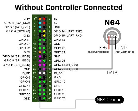
no controller connected

In this configuration, I see the N64 system pull the line high when it's turned on, but there is no data request or any further change.

However, when I additionally attach a controller to all three inputs (data, ground, vcc) like this:
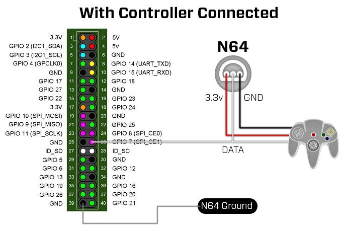
controller connected

I am able to monitor data flowing between the system and the controller with the PI.

So, finally, the question: how is the N64 detecting the controller is connected, and how might I go about emulating that? Is it the resistance between the 3.3v and GND line? Something else entirely?

This is my first post, so let me know if I've betrayed any stack exchange policies, or if you need any additional information.

Thanks for your help!

\$\endgroup\$
8
  • 1
    \$\begingroup\$ Probably through actual participation in the signalling protocol. This is probably too broad to address in an answer here, but there are plenty of resources online and easily found with a web search - for example developer.mbed.org/users/fomartin/notebook/… Note that policies here don't permit answers which merely link to external sites, an answer would have to include enough detail to stand alone, which may be excessive in this case. \$\endgroup\$ Commented Jul 12, 2017 at 18:23
  • 1
    \$\begingroup\$ Hi Chris, thanks for responding! I have looked at many sites including that one, but they all describe the communication from the controller <-> pi, which doesn't include anything about n64 -> controller detection. The controller will always respond to 0x00, and other polling commands correctly from that setup. From what I've read, the n64 system should pull the line down to send the 0x00 "get controller status" command, but I'm not seeing that. My theory is that the n64 won't talk to the controller without some kind of electrical detection first. Does that make sense? \$\endgroup\$ Commented Jul 12, 2017 at 19:31
  • 1
    \$\begingroup\$ You may want to use a storage scope or a cheap USB-based logic analyzer on it. Personally, I'd suspect it would just try to poll every few seconds, as that would be the cheapest scheme to implement. But it could be something with pulling resistors, or power consumption, or unsolicited messages or longer "hey I'm here" pulses from the controller. \$\endgroup\$ Commented Jul 12, 2017 at 19:59
  • \$\begingroup\$ I was hoping to avoid the cost of the logic analyzer, but maybe its time to invest. I'll try recording the communication during boot between the controller and N64 with the PI. Hopefully that will give me enough detail to figure out if there's anything interesting going on that I missed. Thanks! \$\endgroup\$ Commented Jul 12, 2017 at 20:40
  • 3
    \$\begingroup\$ @Transistor Does there exist a publically available datasheet for an N64 controller? \$\endgroup\$
    – Matt
    Commented Jul 12, 2017 at 23:17

1 Answer 1

5
\$\begingroup\$

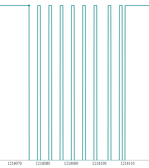
It turns out I wasn't sampling the GPIO long enough. I wrote a little Raspberry PI kernel module to sample the GPIO as fast as possible for 3 seconds, and record a semi-accurate trace. Here's what showed up on the wire after one second:

GPIO trace

In summary, the N64 waits one second after boot to ask the controllers to identify themselves with 0x00 followed by a stop bit.

Thanks Chris Stratton for your help!

\$\endgroup\$
1
  • \$\begingroup\$ Is your code for this available somewhere? \$\endgroup\$ Commented Nov 5, 2022 at 21:31

Your Answer

By clicking “Post Your Answer”, you agree to our terms of service and acknowledge you have read our privacy policy.

Not the answer you're looking for? Browse other questions tagged or ask your own question.