1
\$\begingroup\$

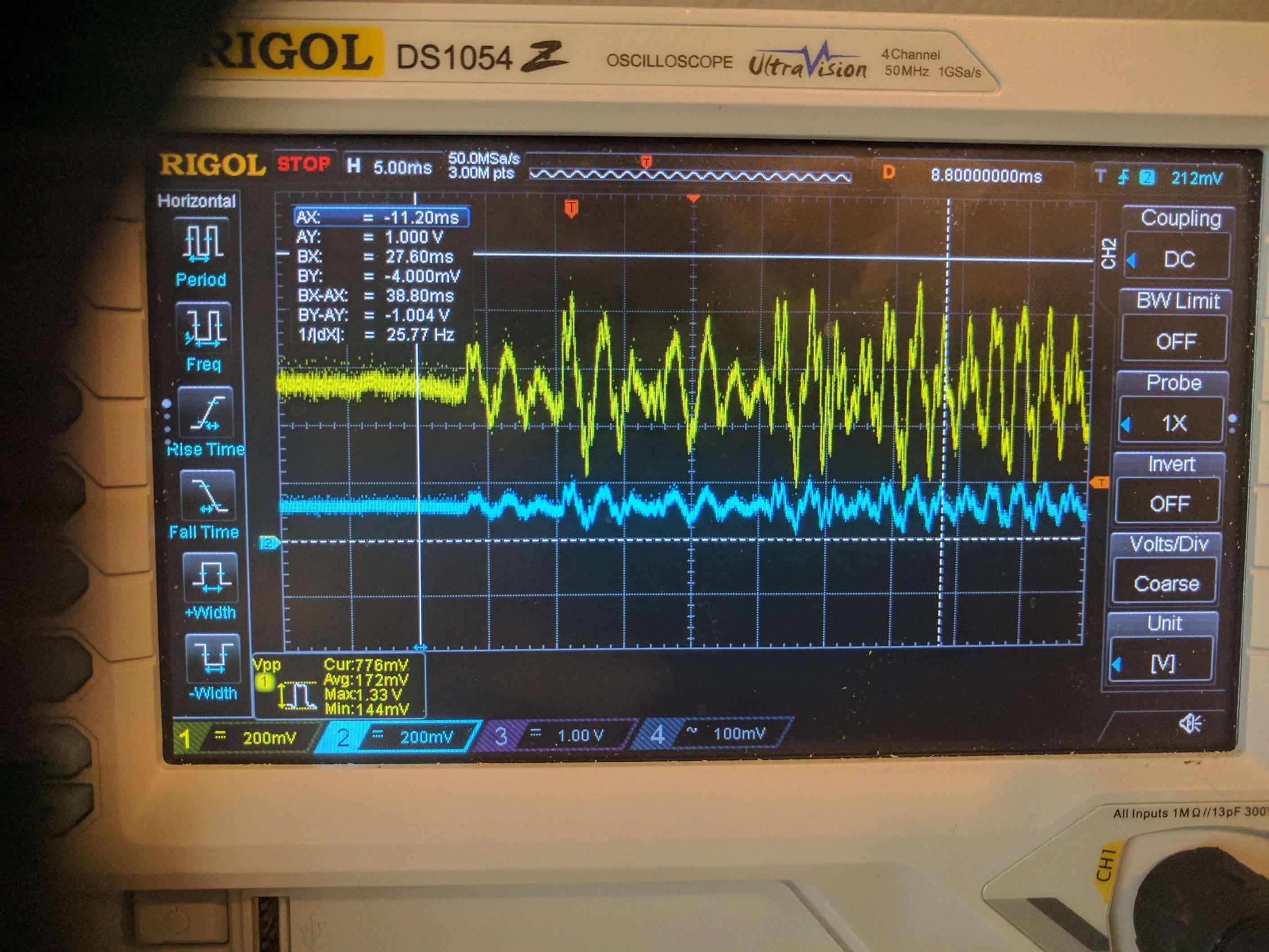
I am trying to amplify a 0.4Vpp audio signal to 1Vpp using OPA344 however my output is clipping around 0.5 volts even though my supply is 3.3v

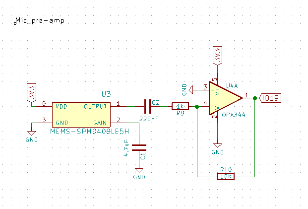
Op-amp is in inverting configuration: enter image description here
blue trace is input, yellow is output. enter image description here

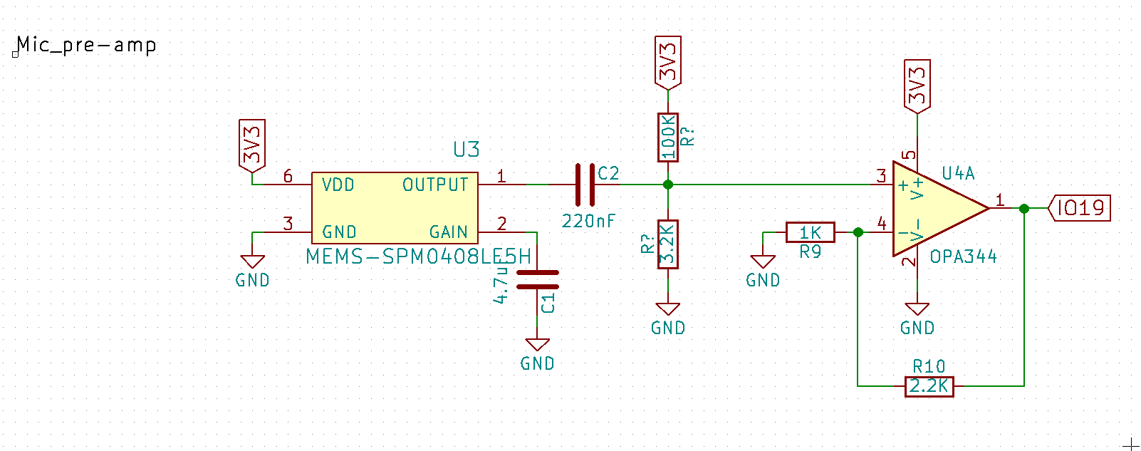
[UPDATE] Fixed - However I'm considering putting the voltage divider on the output so changing the gain won't change the bias

Updated the schematic, this puts me at 1Vpp with a 500mv bias: enter image description here
enter image description here

\$\endgroup\$
8
  • 3
    \$\begingroup\$ On a different note, you need to bias the non-inverting input to Vcc/2 to cope with positive input signals. \$\endgroup\$
    – Transistor
    Commented Jul 28, 2017 at 12:36
  • \$\begingroup\$ As @Transistor said, why is V+ connected to GND? \$\endgroup\$
    – Shamtam
    Commented Jul 28, 2017 at 12:37
  • \$\begingroup\$ @Shamtam V+ isnt connected to ground. Its connected to 3.3 V \$\endgroup\$
    – Matt
    Commented Jul 28, 2017 at 12:39
  • \$\begingroup\$ @Matt: I think he means the positive input \$\endgroup\$
    – PlasmaHH
    Commented Jul 28, 2017 at 12:43
  • \$\begingroup\$ Yep, my mistake! I meant the + input of the amp, not the positive rail. If I had a bit more time I'd actually put together an answer. Short answer to the OP: the lower half of your signal is clipping at the bottom end on the input (when it dips below GND), which is why you see it clipping at 0.5V. \$\endgroup\$
    – Shamtam
    Commented Jul 28, 2017 at 12:44

1 Answer 1

3
\$\begingroup\$

As @Transistor says, you need to put a resistor divider on the positive input of the op amp to bias it to 1.65 volts, so your signal can swing positive and negative about this point. The larger problem is that the negative input is a virtual ground, and by using 220 nf and 1K, your output time constant is 220 usec. You have created a high pass filter around 4500 hz (nothing but high audio will get through). Perhaps you should also consider a non-inverting amplifier.

\$\endgroup\$
1
  • \$\begingroup\$ Updated post with new non-inverting schematic, getting the output I want - just need to add a filter. \$\endgroup\$
    – physiii
    Commented Jul 28, 2017 at 17:03

Your Answer

By clicking “Post Your Answer”, you agree to our terms of service and acknowledge you have read our privacy policy.

Not the answer you're looking for? Browse other questions tagged or ask your own question.