3
\$\begingroup\$

Recently purchased some components from a BOM for restoring an old tube radio, however it got me wondering about the capacitors and the voltage ratings..

Part of the order contained two 10uF electrolytic capacitors but at different ratings, one at 1000V and one at 630V (for what it's worth, the voltage I'm working with here is ~440V). Would it matter if I were to use just two 1000V ones? What are any downsides in using a higher rated capacitor than what is called for?

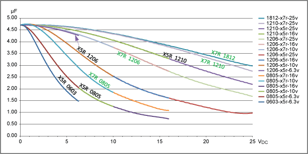
I also stumbled upon this in a similar question that was asked and would appreciate any help in understanding it: enter image description here

My assumptions are: these are all the same ~4.7uF capacitance, just at varying voltage ratings; and a capacitor is inoperable at voltages higher than what it's rated for. So let's compare the two extremes, 0603 and 1812, at ~3V. It seems the capacitance of the 0603 is now ~2.5uF meanwhile the 1812 is still high up at ~4.7uF. This indicates (to me) what should be a noticeable change in behaviour when comparing the two in a 1-5V application. So what would it be?

I know this is pretty loaded and there's a lot of questions going on. I definitely digress here and there, please forgive me. I'd appreciate as much info at a noob-friendly level as possible. Thanks!

EDIT: Here is the post I've already read, also source of image used.

\$\endgroup\$
4
  • 2
    \$\begingroup\$ Your assumptions aren't correct. those numbers, "1206" and "0805" etc are size. The larger the number, the bigger the capacitor. You want higher voltage? You get a bigger capacitor. The other stuff "X5R" / "X7R" is the material quality over temperature and/or how hot or cold it can get, as well as what that means to its values. These are ceramic capacitors, they live by different rules than most of the other types of capacitor. One capacitor is simply not the other. Comparing a ceramic capacitor to an electrolytic one is like comparing a motorcycle to a van. Completely different purposes. \$\endgroup\$
    – Asmyldof
    Jul 31, 2017 at 16:01
  • \$\begingroup\$ @Asmyldof Thanks for correcting the assumptions. Is there a good source that explains the difference between common capacitor types that you can recommend? \$\endgroup\$
    – Capn Jack
    Jul 31, 2017 at 17:17
  • \$\begingroup\$ For an overview of capacitors, see this video. \$\endgroup\$ Jul 31, 2017 at 18:52
  • 1
    \$\begingroup\$ Does this answer your question? Can I use a higher voltage rating when replacing capacitors? \$\endgroup\$ Jul 17, 2022 at 13:15

4 Answers 4

9
\$\begingroup\$

Part of the order contained two 10uF electrolytic capacitors but at different ratings, one at 1000V and one at 630V (for what it's worth, the voltage I'm working with here is ~440V).

If you're sure both have 440V on them, you can use 600V for both, it's likely to be cheaper. I wonder why the original was rated at 1kV.

Would it matter if I were to use just two 1000V ones? What are any downsides in using a higher rated capacitor than what is called for?

Downside is price and bulk. Although modern caps are likely to be smaller than the ones you are replacing, so this shouldn't be a problem.

Now, to add to the other answers...

High-K ceramics like X7R etc are crap dielectrics if you consider the dC/dV, the capacitance varies a lot, it also varies with temperature. Also they are piezoelectric. Never use those in the signal path, for filtering, or for decoupling a high impedance node like a VREF (you'd get a piezo microphone).

So you may wonder why people use them so much. The reason is that they are very good for decoupling power supplies. Since the voltage is constant, dC/dV distortion doesn't matter. And ceramics have many advantages:

They are very cheap and give a high capacitance per volume. They withstand very high temperatures, so they can be surface-mounted directly on the board. This results in very low inductance, which is excellent for decoupling.

Note NP0 ceramics are another story, they are extremely linear and accurate.

EDIT

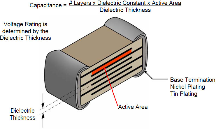
"High-K" means "High dielectric constant". \$ \kappa \$ is basically \$ \epsilon_r \$ Two plates with a bit of dielectric between them make a capacitor of value:

\$ \frac{Area * \epsilon_0 * \epsilon_r}{Thickness} \$

A material which is a good insulator can be thinner, so you get more capacitance per volume.

And a material with high dielectric constant \$ \kappa \$ or \$ \epsilon_r \$ also gives higher capacitance per volume.

Polypropylene has a dielectric constant of 2.2.

Barium Titanate (one of the High-K ceramics) has 7000. So, it packs a lot more capacitance into much less volume.
enter image description here

Plate thickness can get down to 0.5µm these days.

Drawback of these materials is that dielectric constant gets lower with higher electric field. A higher voltage rated X7R ceramic cap (say, 25V versus 6V) will have thicker plates, therefore electric field is lower, therefore its capacitance drops less at the same voltage (say, 3.3V for both caps).

Same if you buy a larger part (1206 is physically larger than 0603 for example) You get thicker plates, and possibly the manufacturer can use a less "extreme high K" material so capacitance drops less.

This explains the curves you posted. Note 1812, 1206 etc are package sizes.

This is off topic relative to your electrolytic caps, but since you asked ;)
\$\endgroup\$
10
  • \$\begingroup\$ Thanks for the explanations to the first half. Your starting paragraph to my other questions is confusing me though.. High-K (you mean high voltage rated ceramics?) has its capacitance vary a lot? But on the chart it looks like they don't... The lower rated ones seems to fluctuate. \$\endgroup\$
    – Capn Jack
    Jul 31, 2017 at 17:28
  • \$\begingroup\$ See new edits ;) \$\endgroup\$
    – bobflux
    Jul 31, 2017 at 18:02
  • \$\begingroup\$ face palm we just went over this last term in circuits... Can't believe I've already forgotten. Thanks for the refresher mate. But now I've had to explanations for the curves, with maths and now with materials. But my main question still stands: What changes would be observed in the circuit between the two? (e.g. if I had a 5V circuit, how would using a ceramic rated for 5V vary from using one rated for 25V? sorry I do appreciate your contribution I'm just really keen to figure this out! \$\endgroup\$
    – Capn Jack
    Jul 31, 2017 at 19:05
  • \$\begingroup\$ Hehe. The ceramic cap rated 25V would lose less capacitance at 5V DC bias than the one rated for say, 6V3. But if you can get a 10µF 6v3 versus a 1µF 25V for the same price and the same size? Then which one will have more capacitance at 5VDC? The headache begins... can't answer this without looking at the curves and all. Point being, if you want some decoupling caps for low voltage, get a roll of a hundred of 1µF 25V, you'll get huge quantity discount... who needs different values LOL \$\endgroup\$
    – bobflux
    Jul 31, 2017 at 19:20
  • \$\begingroup\$ Price aside though, and looking at this at a purely functional level and no practicality; would the 25V ceramic be a better choice? I want to say yes because the capacitance is much closer to what's on the label at 5V than the lower rated one. Is this correct? \$\endgroup\$
    – Capn Jack
    Jul 31, 2017 at 19:27
5
\$\begingroup\$

Several unrelated questions.

Ceramic capacitors suffer from what's called DC bias. The higher the DC voltage across them, the less actual capacitance they have. So your 0805 capacitor at 10V is only 1.5uF effective capacitor. This has to do with how the crystals align in the dielectric which is above and beyond the scope here. Small ceramic caps (NP0/C0G) do not exhibit this effect. Larger caps show this effect less because they have larger volume and hence less capacitance per cubic millimetre than the smaller physical sizes. They can also be manufactured for higher voltage tolerance for the same reason.

With electrolytes it depends if there's any downside. You'd have to check the capacitor datasheet. As a rule of thumb, same diameter cans have similar ESR and hence would work more or less the same in high-current-ripple applications (=SMPS). I don't think tube radio qualifies as high ripple current.

Nb, capacitors at large voltages are dangerous, you can kill yourself with a 47µF capacitor charged to 440V. I'd hate to try that with 4.7µF either. Pain threshold at 400V is 28 nano farads.

\$\endgroup\$
2
  • \$\begingroup\$ Thanks again. Would you mind going into further detail on " Larger caps show this effect less because they have larger volume and hence less capacitance per cubic millimetre than the smaller physical sizes."? That explains the higher capacitance but how does this affect the circuit compared to a small cap? \$\endgroup\$
    – Capn Jack
    Jul 31, 2017 at 17:23
  • \$\begingroup\$ @CapnJack you can see it in the chart you included. Physically larger 1812 cap retains more of its capacitance at higher voltages than the much smaller 0805 cap. Less layers, bigger dielectric layers translates to lesser bias effect. Physically larger capacitor does not necessarily have more capacitance, it can be more "sparse". That usually translates to higher breakdown voltage too as the insulating layers are thicker. \$\endgroup\$
    – Barleyman
    Jul 31, 2017 at 21:24
3
\$\begingroup\$

To answer the ceramic capacitor part of your question ...

As the manufacturer tries to push more uFs into a smaller space, he has to use a higher K ceramic. Generally, the higher the K, the worse the voltage sensitivity.

This is why it's essential when specifying ceramic capacitors, if capacity reduction with voltage is an issue, that you specify a specific case size from a specific manufacturer in a specific value and voltage rating.

In the same voltage and capacitance rating, as the case size falls, the voltage sensitivity will increase, even if the ceramic has the same designation ( the X7R or Y5U bit). This designation covers only the tempco, NOT the voltage sensitivity.

\$\endgroup\$
2
\$\begingroup\$

Can you say "distortion"? The classic equation Q = C * V, differentiated against time, becomes

$$ dQ/dT = C * dV/dT + V * dC/dT$$

However, we can differentiate against voltage (change in voltage), and we get

$$ dQ/dV = C * dV/dV + V * dC/dV$$

The first term is "C * 1" as we expect to describe stored charge.

That second term "V * dC/dV" is the distortion. For that leftmost capacitor, in the 2 volt and 3 volt region, the dC/dV is 30% per volt. Lots of charging error there.

\$\endgroup\$
1
  • \$\begingroup\$ Thanks for pointing this out! Now the drop in capacitance makes sense \$\endgroup\$
    – Capn Jack
    Jul 31, 2017 at 17:29

Your Answer

By clicking “Post Your Answer”, you agree to our terms of service and acknowledge you have read our privacy policy.

Not the answer you're looking for? Browse other questions tagged or ask your own question.