0
\$\begingroup\$

Looking for a simple circuit which output is only active when its input is a low frequency (0.2-0.5Hz) pulse. The circuit output should be deactivated if input is unchanging.

I tried monostable 555 circuit, but its output is active as long as input is zero. I also tried a capacitor between input and pin 2, but then the circuit doesn't stay active when pulsing - it switches off and immediately activates, which is not what I want.

\$\endgroup\$
14
  • 3
    \$\begingroup\$ solution is a 5 second retrigerable one shot design \$\endgroup\$
    – D.A.S.
    Commented Aug 21, 2017 at 21:05
  • 3
    \$\begingroup\$ easy with a microcontroller. Be aware that you need to wait at least 5 whole seconds to be sure there's no further 0.2 Hz signal. If you don't want a single isolated pulse to trigger, you also need to wait 5 seconds to be sure the signal is periodic. It's often not easy to even specify what constitutes desired behaviour. \$\endgroup\$ Commented Aug 21, 2017 at 21:05
  • 2
    \$\begingroup\$ or: buy a microcontroller with a watchdog. This is fairly common to have in hardware. \$\endgroup\$ Commented Aug 21, 2017 at 21:07
  • 2
    \$\begingroup\$ then I'd rather fix my watchdog timer code than add another source of bugs (an analog watchdog). It is extremely unlikely your microcontroller's WDT is buggy, compared to the likelihood of a self-build analog watchdog to malfunction, if you ask me. \$\endgroup\$ Commented Aug 21, 2017 at 21:11
  • 2
    \$\begingroup\$ consider CM chokes on inductive twisted pairs, improved grounds and shields with C feedthru shunt caps to cure EMI. Any CMOS 1shot design for 5 seconds can work with adequate pulse width to set timer. \$\endgroup\$
    – D.A.S.
    Commented Aug 21, 2017 at 21:13

1 Answer 1

4
\$\begingroup\$

Folks are right. Most MCUs do have a built-in watchdog and it's better to use that if possible, and also fix your (probably HW) problem first. Also, if you Google "watchdog ICs" and you will see many made by different manufacturers.

But if you really want to roll your own cuz it's just fun and hacker-like, there are many, many ways to implement this. Basically the idea 1) make a timer that gets constantly reset by the pulses, 2) does not care if the pulse stops low or high.

Here's a totally discrete solution.
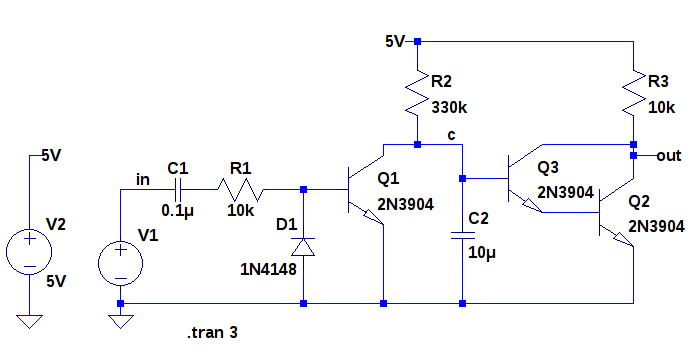
Watchdog Circuit Schematic

On a rising edge, C1 charges up and current flows into Q1 base, turning Q1 on. This discharges C2, keeping Q3/Q2 turned off.

On a falling edge, the charge left in C1 is discharged through D1 so it's quickly ready to cycle again.

If pulsing stops, then Q1 is never turned on and C2 slowly charges up through R2. When its voltage reaches about 1.2 Volts, the Darlington Pair Q3/Q2 turns on and pulls the output low.

Here's a simulation of the circuit with the watchdog signal getting stuck high:
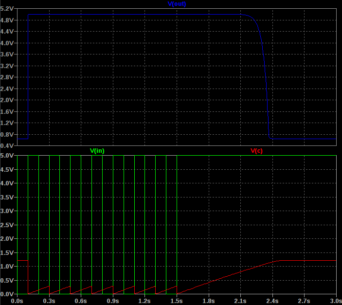
Watchdog Circuit Simulation

Most MCUs reset lines are active low so this is geared for that.

You might want to tie R2 to a GPIO line instead of 5V so that you can enable this watchdog circuit only after you are ready (e.g. OS is booted and your code is running).

This might seem like an expensive complicated solution but this is actually cheap because small transistors are pennies, and small caps and resistors are less than a penny. But it does cost you board space and parts count though.

You can adapt this circuit also. For example, you can use the C1/D1 type of architecture to constantly reset a 555 timer.

By the way, you should also check 1) how you're routing the crystal on your MCU. Make sure the capacitors of the crystal are grounded right to the MCU and no other fast rising signals run near your crystal, and 2) make sure your reset line has a good enough pullup, and 3) make sure your power is clean. Put a scope on your supply and see if there are any glitches causing the rail to dip and MCU to brown out.

\$\endgroup\$
2
  • \$\begingroup\$ Thank you! Crystal is routed close-up, but there's no pullup on reset, it is floating. Datasheet for AT90USB647 says it has internal pull-up. No scope unfortunately, so #3 is impossible. Also it worked in 24/7 mode without issues for 59 days, so those glitches are very rare. \$\endgroup\$
    – George Y.
    Commented Aug 22, 2017 at 0:41
  • 1
    \$\begingroup\$ Is it possible your code accidentally turns on more than one solenoid at same time and caused brown out? For example, a round off error in your time calculation, or perhaps the time server added or subtracted a leap second causing your time calc to get a bit off? I used to work on cell phone ICs and we had HW registers to tell us if the watchdog tripped because of brownout, code crash, overheating, etc. We would also write log files periodically in case of a crash. Too often can wear out your SD or EEPROM though. \$\endgroup\$ Commented Aug 22, 2017 at 18:19

Your Answer

By clicking “Post Your Answer”, you agree to our terms of service and acknowledge you have read our privacy policy.

Not the answer you're looking for? Browse other questions tagged or ask your own question.