1
\$\begingroup\$

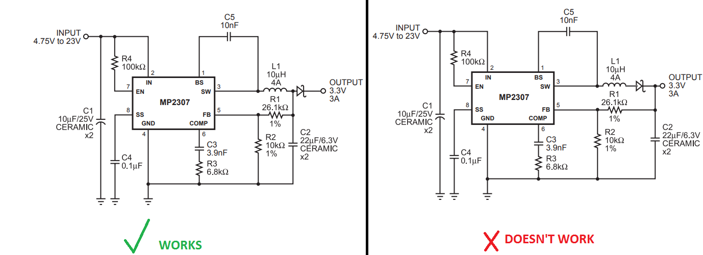
Why doesn't work the second version? If I try this version no voltage on the output. Why?

I would like to make a reverse polarity protection, but the problem with the first version: in idle mode there is a voltage e.g: 12.00V, but when I connect a variable load the voltage decreases when the current increases, because more voltage drop on the schottky-diode. I would like to use a reverse polarity protection but I don't want that voltage drop vs current increase. I can't use a mosfet because I use 1V output voltage too.

enter image description here

\$\endgroup\$
2
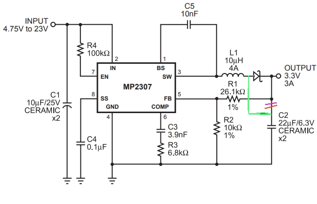
  • \$\begingroup\$ Try moving the top of C2 left of the diode in the right circuit, keeping the resistor chain as is. \$\endgroup\$
    – Trevor_G
    Commented Sep 1, 2017 at 20:04
  • \$\begingroup\$ The second version doesn't work because you broke the entire circuit, the entire idea of buck converter, by blocking half currents through the inductor. \$\endgroup\$ Commented Sep 1, 2017 at 21:30

3 Answers 3

2
\$\begingroup\$

As John D mentions you can't have a diode before the regulator cap since the device will try to pull charge from the cap when the voltage is detected as being too high.

Try moving the top of C2 left of the diode in the right circuit, keeping the resistor chain as is.

enter image description here

ADDITION: Generally the idea of preventing back drive like that can be problematic. On light loads with any substantial capacitance after the diode, the voltage may creep up higher than you want past the diode. Some additional over-voltage protection may be prudent.

\$\endgroup\$
1
  • \$\begingroup\$ @Lobi if you hook up a 12V car battery backwards to that output you will fry a lot more than that regulator. However, if you are concerned add another shotky pointing upwards in parallel with R2. \$\endgroup\$
    – Trevor_G
    Commented Sep 1, 2017 at 20:31
4
\$\begingroup\$

The MP2307 is a synchronous buck converter. At light or no load, the part will draw current from the output cap to maintain regulation. (The low side FET turns on, reversing the current direction in the inductor, and pumping up the input caps.)

By putting the diode in the control loop before the output caps, the part has lost its ability to pull negative current through the inductor.

This likely causes the output caps to rise each switching period until the part reaches OVP protection and shuts down. Or, it could cause a control-loop instability which shuts the part down for other reasons.

Look at the startup with a 'scope to see what happens if you want to know, but this topology (especially without a light-load PFM or diode-emulation mode) can't work with a diode where you want to put it.

\$\endgroup\$
1
\$\begingroup\$

SW output (pin 3) is a half bridge FET driver going between Input (p2) then to ground (p4) at some PWM clock rate and duty cycle. Therefore inserting a diode as you have shown blocks current in one direction.

With a Pch FET on high side output or Nch FET on return side, you can get better reverse protection with low If*RdsOn= Vdrop.

N.B. This also protects the FB input from reverse voltage.

See here for details.

http://www.ti.com/lit/an/slva139/slva139.pdf

\$\endgroup\$
3
  • \$\begingroup\$ no can do at the moment on iPad. the link explains eveything \$\endgroup\$
    – D.A.S.
    Commented Sep 1, 2017 at 21:04
  • \$\begingroup\$ why is 1V not in question, why do you need output reverse protection at 1V? \$\endgroup\$
    – D.A.S.
    Commented Sep 1, 2017 at 21:27
  • \$\begingroup\$ Did you not see the schematic in my link? Your question is ambiguous if it shows 3.3Vout \$\endgroup\$
    – D.A.S.
    Commented Sep 1, 2017 at 21:48

Your Answer

By clicking “Post Your Answer”, you agree to our terms of service and acknowledge you have read our privacy policy.

Not the answer you're looking for? Browse other questions tagged or ask your own question.