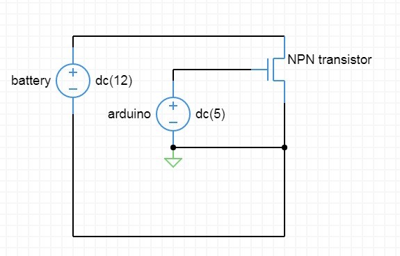
I need a transistor as a switch. I need to power a motor with a 9 v battery and on or off the circuit using a 5v signal (from an arduino board). I don't which NPN transistor to choose. (I don't know how to use sandbox properly so there might be some mistakes in the diagram. )
I need a list of NPN transistors suitable for the job. (Sorry it 9v not 12 v). The current through the motor is about 0.75A.Thanks in advance!
-
\$\begingroup\$ That's not an NPN transistor. It's a n-channel MOSFET. Beside, in the schematics the motor is missing... \$\endgroup\$– next-hackCommented Sep 3, 2017 at 8:15
-
\$\begingroup\$ If you were to go the BJT route, you look for a generic NPN-darlington like a TIP120 \$\endgroup\$– sstobbeCommented Sep 3, 2017 at 16:36
3 Answers
If the motor is very small toy motor (say 500 mA max), try a 2N2222a (maximum continuous collector current (Ic) = 800 mA). The transistor will probably need a heat sink. If the motor draws 500 mA, the headroom will be 300 mA.
Thanks @next-hack. I pulled out a Mims book to read more about this topic. On second thought, a MOSFET such as the IRF510PBF is cheaper and probably won't require a heatsink because it has a TO-220AB package.
Thanks @peufeu. After your comment, I looked closer at the IRF510. So, I now have to also say the IRF510 won't work because of the RdsON in this circuit.
If @user161778 were using a '130 size' DC hobby motor, the currents could be 70, 250 and 500 mA (no load, loaded and stalled). But, the current stated is 750 mA. So, it will be interesting to see if the circuit is built with an NPN (such as the 2N2222) or a MOSFET (such as the AO4480).
Great link for additional reading.
-
4\$\begingroup\$ That's not a good answer. 1) The 2N2222 is not suitable to drive a 500-mA motor. If you see the datasheet, at 500mA the saturation voltage will be 1.6V, and this could fry your 2N2222 (TO18 heatsinks are quite rare and have a poor performance). Beside, the 800mA is the absolute maximum rating. 2) Without a resistor between the base and the Arduino, chances are that you'll fry the 2N2222 and/or the Arduino. \$\endgroup\$ Commented Sep 3, 2017 at 8:21
-
1\$\begingroup\$ IRF510 requires 10V gate drive, won't work, you need a logic level FET... There are thousands, at the currents involved here a SO-8 like AO4480 will do the job just fine but feel free to use any part from a local dealer with RdsON specified for Vgs=5V to less than about 50 mOhm. If RdsON is specified only for 10V Vgs it wont work... \$\endgroup\$– bobfluxCommented Sep 3, 2017 at 15:13
Your circuit has several flaws.
- That's not an NPN transistor. It is an n-channel MOSFET.
- There is no motor. In that circuit you're just "shorting" (in case of an ideal MOSFET) the 9-V supply.
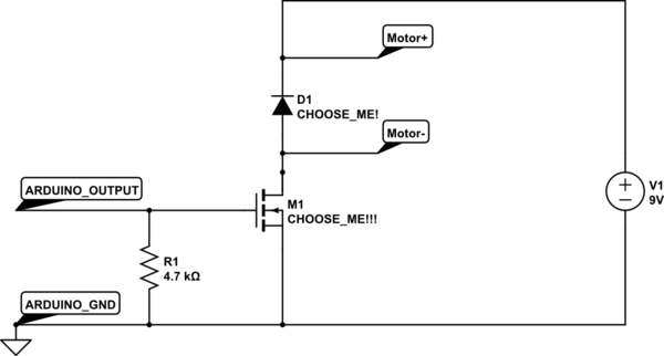
- There is no flyback diode. Unless you're using very fancy motors (e.g. piezoelectric), I assume you're using a electromagnetic motor. Therefore it will exhibit inductive behavior. Once you turn off your MOSFET/NPN transistor, the motor's inductance will try to keep the value of the current that was flowing into it (Faraday-Neuman-Lenz law). To do this, it will create "whatsoever" voltage it requires to force such current. Eventually this will reach the MOSFET/NPN breakdown voltage, which is not good.
- There is no pull-down resistor on the Arduino Pin. When the Arduino is in the reset state, all its I/O pins are configured as input without pull-up (the problem is even worse if the pull-up were enabled). This means that the base/gate is floating and ready to pick up all the noise. This is very dangerous as at best the motor could simply turn on (or even better, nothing occurs), at worst, the BJT/MOSFET will blow out, because you're bringing it in the "amplification" region (linear region for BJT, saturation region for MOSFET). In such region, high currents and voltages are simultaneously present, so the power dissipation is huge (you don't want this on a switch!).
I suggest you not to use a BJT, especially for relatively high-current motors. In fact, you'd need a power BJT, but power BJTs have a very poor current gain, therefore the base current should be quite high. The arduino GPIO pin might not provide enough current to fully turn on your BJT. Using a darlington transistor would not help too much, as its saturation voltage is quite high: you would need a very big heatsink.
Use instead a n-channel, LOGIC-LEVEL (i.e. low threshold voltage), low Rds(ON), power MOSFET. Which one depends of course on your requirement! Digikey or Mouser have good search engines.
The final schematics should be:

simulate this circuit – Schematic created using CircuitLab
You must choose the MOSFET and also the diode, based on the motor current specifications (yes also on the voltage, which is pretty low in your case).
The 4.7k Ohm resistor ensures that the Arduino I/O stays low (not to turn-on the MOSFET) even if you accidentally configure the pin as an input with pull-up.
If the motor is a very low power one, then you can use a BJT, instead of the MOSFET, provided that you put a suitable series resistor between R1 and the base of the BJT!!!
EDIT: If the 9V battery you're referring to is a standard PP-3 battery, then I assume your motor has a very low current. In fact, such batteries have a very limited output current capability. In that case a BJT like BC337-40 might work for you. The diode and the two resistors (one is R1, an the other - not shown for the MOSFET, but it's in series to the base of the BJT) are still required.
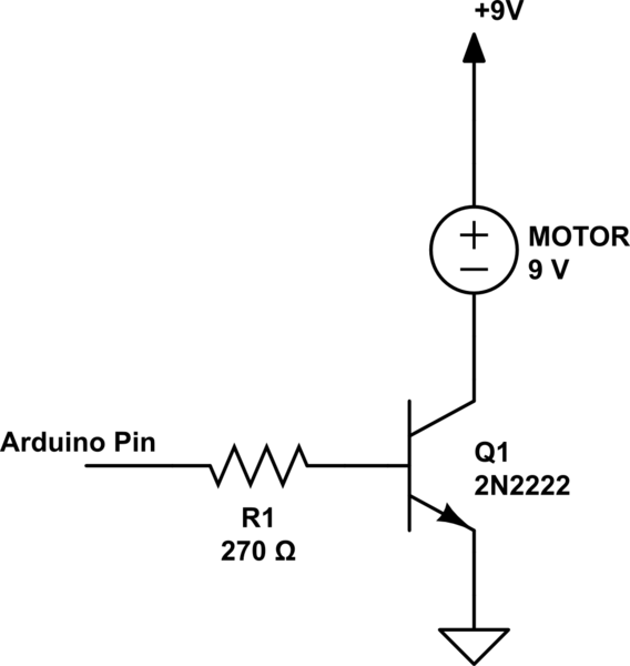
In addition to John Sanelli's answer, the connection diagram could be something like this:

simulate this circuit – Schematic created using CircuitLab
[Edit] Changed R1 from 100R to 270R to not overstress the pin driver.
Actually, I'm not saying that this is a particularly good way to connect it, and I'm not sure if 2N2222 is actually good enough for the job. But if you're going to drive a (small) load with an NPN transistor, then this connection diagram is basically the way to do it. Choose a larger R1 if you can and use a transistor that is good enough for whatever job you're doing. Or swith to using a power FET or IGBT or a relay if you're driving anything that needs more than a little amount of power.
-
3\$\begingroup\$ You might want to explain why you chose 100 ohms, and whether or not it is a safe value for the Arduino. \$\endgroup\$– user16324Commented Sep 3, 2017 at 8:55
-
1\$\begingroup\$ @BrianDrummond is absolutely correct. Basically I wanted to keep the circuit as simple as possible as not to distract the readers' thoughts from what is the most essential. R1 at 100 ohms is a bit brutal, but the protection structures in the IO pin should be capable to sink the transients. I chose 100 ohms to make sure there is sufficient base current to quickly saturate Q1 (not sure if it's correct word for bipolar) e.g. to make sure there is enough base current. In reality, I'd examine the transistor (not sure 2N2222 is good or not) beta value and choose higher R and add protection diodes. \$\endgroup\$– PkPCommented Sep 3, 2017 at 12:10
